
Abstract
This study offers a thorough simulation test on the behavior of materials resistant to earthquakes, with an emphasis on the creative use of high-ductility nano-based cement and its possible use in home constructions. Globally, earthquakes continue to pose serious risks to people’s lives and infrastructure, which makes it necessary to create cutting-edge building materials and methods to increase seismic resilience. In this work, we use a battery of accurate models and tests to examine the mechanical characteristics and seismic resistance of high ductility nano-based cement. To evaluate the material’s behavior under various earthquake scenarios, our study combines seismic testing, structural analysis, and material characterisation. We also investigate the possibility of employing this innovative cement in the building of house buildings in an effort to improve their seismic resistance while preserving sustainability and cost-effectiveness. According to the study’s findings, high ductility nano-based cement has a lot of promise for enhancing housing constructions’ resilience to earthquakes by providing better ductility, durability, and structural integrity. Additionally, the research emphasizes how critical sophisticated modeling methods are to assessing earthquake-resistant material performance and practical applications in actual building projects. These findings offer insightful information to the building sector, opening the door for the use of cutting-edge materials that can help build safer and more durable homes in seismically vulnerable areas.
Keywords: Simulation Analysis, High Ductility, Nano-Based Cement, Structural Performance, Nano Carbon Tube Earthquake-Resistant Materials.
Introduction
An developing discipline in engineering is nanotechnology. The advancement of superior instrumentation and the development of nanotechnology in the field of material science have opened the door for its use in the building industry [1]. The structural and nonstructural characteristics of cement paste, mortar, and concrete are significantly altered when nanoscale particles are included into cement composites [2]. The particles’ surface area is increased as they are downsized from micron to nano size [3]. An increase in surface area results in morphological changes, an increase in chemical reactivity, structural modifications to cement hydrates, and an improvement in the characteristics of concrete. There are two ways to make nanoparticles. In the “top down” technique, larger particles are shrunk to smaller ones without changing their original qualities, but in the “bottom down” approach, incredibly tiny nanoscopic molecules and atoms combine to form larger structures, which allows the properties of the individual particles to be changed [4] [5]. The qualities of typical grain size materials with the same composition can be dramatically enhanced by nanoscale particles. Unique physical and chemical characteristics of nanomaterials can help create materials that are more efficient than those that are already on the market. With the required stress-strain behavior, concrete made with nanomaterials is stronger and more resilient.
Even though the study is primarily concerned with mechanical qualities, it might be difficult to comprehend precise laws. CNT-reinforced cement-based materials have not been well studied in terms of their implications on the environment and human health [6]. The macroscopic characteristics of these materials have mostly been the subject of prior study. The project looks at the durability and technical properties of concrete combined with hybrid nanomaterials, specifically CNT and nano-clay [7]. According to the research, adding CNT to NC concrete improves its microstructure, mechanical characteristics, resilience, and resistance to corrosion, which leads to improved performance in terms of mechanical potency and lifespan features [8]. Unevenly distributed CNT particles from additional CNT additions can form clumps, which increase air gaps and reduce strength [9]. The strength improvement is lessened by the addition of 0.04% CNT particles with poor dispersion [10].
Given the rising frequency of seismic occurrences throughout the world, there has been a lot of study and development on earthquake-resistant building [11]. Traditional building materials sometimes fall short of providing the required resilience to resist earthquakes’ destructive powers. With an emphasis on nanocarbon-based cement materials because of their remarkable mechanical qualities, there has been an increase in interest in nanotechnology-based solutions in recent years [12]. Attention has been drawn to nanoparticles like carbon nanotubes (CNTs) and graphene for their potential to considerably improve the mechanical characteristics of cementitious materials [13]. These nanoparticles can increase tensile and flexural strength, ductility, and fracture toughness in cement composites when appropriately disseminated and incorporated.
Studies have shown that cement with a nanocarbon basis may be useful for building earthquake-resistant structures. CNTs, for example, have demonstrated impressive reinforcing effects in cement composites, significantly decreasing fracture propagation and enhancing overall structural performance [14]. Furthermore, these materials’ high electrical conductivity creates opportunities for self-sensing constructions that can give immediate feedback on their structural soundness. Despite the potential benefits of nano carbon-based cement materials, there are still issues to be resolved, such as establishing uniform dispersion, resolving financial concerns, and determining long-term durability [15]. Further research is needed to determine how these materials are used specifically in housing constructions because their performance may differ depending on the design, load-bearing specifications, and climatic conditions.
Literature Review
In 2021 Sajedul Huq et al. [16] established the minimal uniform elongation and fracture elongation necessary for high-strength reinforcing bars to be used in earthquake-resistant constructions. Axial loads other than the weight of the loading device and one’s own weight were not applied to the walls. The T-shaped walls, which had concrete with a stipulated compressive strength of 8 ksi (55 MPa), had a stem that was 100 inches long and one flange that was 100 inches long and 10 inches thick. The nominal shear span for each wall was 300 in. (7620 mm). The standard Grade 60 (420) reinforcement used to build the control specimen T1 matches to the reinforcement’s stipulated yield stress. Walls T2, T3, T4, and T6 were built with reinforcement of Grade 100, and T5 with Grade 120.
In 2021 Silva et al. [17] presented two suggestions for novel wall systems for masonry infills that will be encased by RC frames in order to encourage innovation in brick masonry infills. The findings of an extended experimental campaign are addressed in relation to the mechanical characteristics of the masonry assemblages and the two novel masonry infill wall systems. For additional numerical simulations and analytical analysis of the masonry infill systems, as well as for further in-plane and out-of-plane practical testing to be performed on the masonry infill walls, the data presented in this study is crucial.
In 2020 Papavasileiou & Charmpis [18] proposed the seismically built structures with either steel-only or steel-concrete composite columns. The evaluated building designs are acquired using a structural optimization technique to ensure an impartial comparison of these two design approaches. As a result, any prejudice that may arise from a certain designer’s skills, experience, or subjectivity is prevented.
In 2023 Samuel et al. [19] erected using diagonal rebars in the flexure and shear zones, whereas the remaining two were built without diagonal rebars in the shear zone. The following set of six beams was built in the same way, but with the web enclosed in concrete. After that, all the beams were tested. The test specimens were constructed using 40% less cement and 40% more fly ash, a pozzolanic waste byproduct of thermal power plants. Investigations were conducted on the CFS beam’s failure properties, load-deflection behavior, ductility, load-strain relationship, relationship between moment and curvature, and lateral stiffness.
In 2021 Rong et al. [20] proposed the high performsnce of concrete face rockfill dams (CFRDs) made of geosynthetic-reinforced soil structures (GRSS) is assessed from a stochastic viewpoint. Based on a spectrum expressionrandom function non-stationary model, several groups of seismic ground movements are produced. This study, which uses the Gushui CFRD as an example, uses the generalized probability density evolution method (GPDEM) to compute the failure probability of each damage level of non-reinforced slopes and reinforce slopes. Reliability analysis is given through a number of assessment indicators.
In 2023 de Salles et al.[21] developed the PBD optimization of irregular structures subjected to seismic excitations is presented. The framework is capable of handling tens of thousands of discrete design variables and thousands of DOFs. A Model Order Reduction (MOR) strategy based on the Well-Conditioned Asymptotic Waveform Evaluation (WCAWE) approach is combined with a hybrid optimization algorithm that combines a local optimizer with a restart strategy to reduce the computational burden and enable the problem to be solved. The former is used to accelerate the frequency-domain response, whilst the latter enables dealing with a non-convex and multimodal objective function with multiple discrete variables.
In 2022 Nady et al. [22] developed the twelve irregular building models were subjected to a thorough structural study to determine the impacts of the placement of mass, stiffness, setback, and combined irregularities on the structural seismic response. An irregularity index is presented to measure the consequences of the size and position of different forms of vertical irregularities based on the dynamic features of the structure. The suggested index was effective in estimating all varieties of vertical abnormalities.
In 2021 Sarcheshmehpour [23] proposed to create steel framed tube tall structures that function optimally, the importance of the life cycle seismic risk costs is examined. Three strategies code-based, cost-based, and fixed weight strategies—are used to create the best designs for typical 20- and 40-story structures. While the second and third procedures take into account the overall cost of the structure during its lifetime, the first strategy just reduces the project’s initial cost. Seismic life cycle cost analysis is performed using the Endurance Time (ET) approach. Gradient-based techniques are used to solve the resultant problem when the building code requirements are interpreted into optimization constraints.
In 2021 Rahmi et al. [24] examined to build earthquake-resistant homes in Mentawai using lightweight bricks. A reading of the literature, an inspection of the site, and brick testing in a lab are all part of the research technique. The study discovered that lightweight bricks, which lower the total weight of the structure while retaining its structural integrity, are an appropriate material for building earthquake-resistant homes in Mentawai.
In 2021 Bamanikar & Khurd [25] subjected to nonlinear dynamic analysis using various algorithms and with and without shear walls. The IS 1893-2016 is the most recent edition, therefore to be aware of new provisions, this code is taken into consideration. Additionally, it is important to be aware of other nations’ use of Eurocode 8 from 1998. It is widely accepted that the most accurate approach for modeling the reaction and behavior of structures subjected to high levels of seismic stimulation is the nonlinear time-history analysis method. There are two different analytic techniques: a linear technique and a nonlinear technique. There are subtypes of static and dynamic analysis in both linear and nonlinear analysis.
Problem Statement
Residential structures in seismically active locations are seriously at risk for structural failure and safety. The inability of current earthquake-resistant building materials and methods to provide the required level of resilience has been clearly shown. In order to improve the seismic performance of dwelling buildings, it is important to investigate novel solutions. A potential material for this use is high ductility nano-based cement, according to earlier investigations. But there is still a lack of thorough testing and validation. Widespread use of high-ductility nano-based cement in home building is significantly hampered by the lack of thorough modeling experiments and empirical evidence on its performance in earthquake scenarios. It is crucial to comprehend the behavior of this novel material under seismic stress circumstances as well as how it interacts with conventional construction techniques.
Objective of Study
With a focus on the novel use of high-ductility nano-based cement in housing constructions, the main goal of this research is to conduct an extensive simulation test on the performance of earthquake-resistant materials. This study aims to address the pressing need to increase the stability of residential buildings in earthquake-prone areas. The goal is to make housing constructions safer and more robust by bridging the gap between research and actual application. High ductility nano-based cement will be incorporated into housing constructions as part of this study, which will assess how well it performs and how long it lasts. This will provide researchers important information about whether they can use this cement in actual construction projects. The goal of the research is to ultimately contribute to the development of earthquake-resistant construction techniques that can improve the structural integrity and safety of residential structures in seismically active regions.
Methodology
Investigations are made on the quality and functionality of concrete structures made from multi-walled carbon nanotubes (MWNTs), carbon nanotube composite filler, cement, silica fume, water, sand, and water-reducing chemicals.
Production of nano based cement
The manufacture of carbon nanotube (CNT) cement, commonly referred to as cement with a nano carbon basis, is a developing area in materials science and building technology. When added to cement, carbon nanotubes, which are tiny cylindric structures comprised of carbon atoms, can improve the substance’s mechanical, electrical, and thermal characteristics. An outline of the manufacturing process for cement made from nanocarbon is provided below:
Synthesis of Carbon Nanotubes (CNTs): The most common ways to make CNTs involve laser ablation, arc discharge, or chemical vapor deposition (CVD). By using these techniques, nanoscale nanotubes are produced.
Functionalization: The functionalization of CNTs is a possible step after their production. It is possible to increase the compatibility of CNTs with the cement matrix and the bonding between CNTs and cement by functionalizing them by adding chemical groups to their surface.
Cement Mix Preparation: The same steps are used to make regular Portland cement (OPC) or different forms of cement. To attain consistent characteristics, the CNTs must be evenly distributed throughout the cement mixture.
Mixing CNTs with Cement: Next, the cement matrix is incorporated with the functionalized CNTs. For CNTs to have the greatest impact on the qualities of the material, adequate CNT dispersion must be achieved throughout the cement matrix.
Testing and Characterization: The resultant nano carbon-based cement is examined and evaluated to gauge its mechanical toughness, electrical conductivity, thermal characteristics, and other pertinent characteristics. Compression tests, electrical conductivity tests, and thermal conductivity tests are only a few of the testing techniques used to evaluate the performance of the material.
Optimization: The production procedure may be adjusted to get the optimum results, depending on the intended use and required qualities. Changing the CNT concentration, functionalization methods, and curing procedures may be required.
Scaling up and commercial manufacturing: Once an effective formulation is found, the production method may be expanded for usage in the marketplace. Different formulas, such as high-strength concrete, conductive concrete, or thermally insulating concrete, may be created by businesses and researchers for use in a variety of purposes.
Simulation software
A valuable tool for both engineers and academics in the field of concrete structural analysis is the creation of a 3D finite element model using the Abaqus program. The geometry, limits, and loads that are crucial for comprehending how concrete buildings behave may be precisely defined with this software program. The connecting structure is a crucial component, and in Abaqus, it is frequently accomplished by inverted channels. With regard to elasticity, Poisson’s ratio, and strength characteristics, accurate description of the properties of concrete is crucial. The von Mises yield criteria and the isotropic stiffness law were used in this work to predict concrete behavior.
The structure was broken up into designated components to accommodate for geometric nonlinearities in deformation analysis. By giving control over element size and shape, mesh generation in Abaqus is an essential step in obtaining correct results. The finite element model’s ability to represent the structure’s fine intricacies is guaranteed by appropriate meshing. In order to model the structural behavior that would really occur in the real world, boundary conditions were used, including changes in temperature and external forces. This all-inclusive strategy made it possible to specify loads’ size, direction, and distribution with precision, improving the analysis’s overall accuracy.
Abaqus provides a flexible range of analysis methods, such as static analysis to evaluate how the structure responds to steady-state loads and dynamic analysis to examine how it behaves in the face of time-varying loads or seismic occurrences. To assess the performance of the structure and pinpoint possible failure mechanisms, stress, strain, displacement, and deformation graphs were created. The high friction inherent in the contact components and surfaces between steel and concrete made use of the asymmetric Newton-Raphson technique particularly pertinent in this investigation. concrete behaves in a nonlinear manner, particularly under stress and failure. Through methods like as plasticity, damage, and fracture models, Abaqus enhances the simulation of this behavior. We can better understand the behavior and safety of concrete structures thanks to nonlinear analysis, which goes beyond the limitations of linear elasticity and offers insightful information about the structural reaction in difficult circumstances. Abaqus’ sophisticated concrete structural analysis tools and capabilities are a priceless resource for the building and engineering industries, allowing for the exploration of complex scenarios and ensuring the robustness and safety of concrete structures in a variety of applications.
Model description
Using Abaqus software, various crucial elements and parameters were established in the finite element analysis (FEA) model of a T-beam made of nano-based cementitious material. These included the T-beam’s dimensions, such as its length, breadth, and height, as well as the cementitious material’s material characteristics, taking into account the material’s distinctive features and mechanical behavior at the nanoscale. The discretization method, which aimed to strike a balance between precision and computing effectiveness, was carefully chosen. In order to evaluate the performance and structural integrity of the T-beam, boundary conditions and loading conditions were put up to model the real-world structural reaction of the T-beam under various situations. The goal of the FEA model was to maximize the structural design and durability of the T-beam by utilizing the cutting-edge features of nano-based cementitious materials, and to offer useful insights for engineering and construction applications.
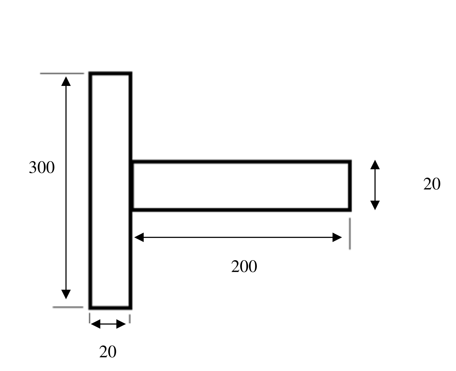
Figure 1: Material model
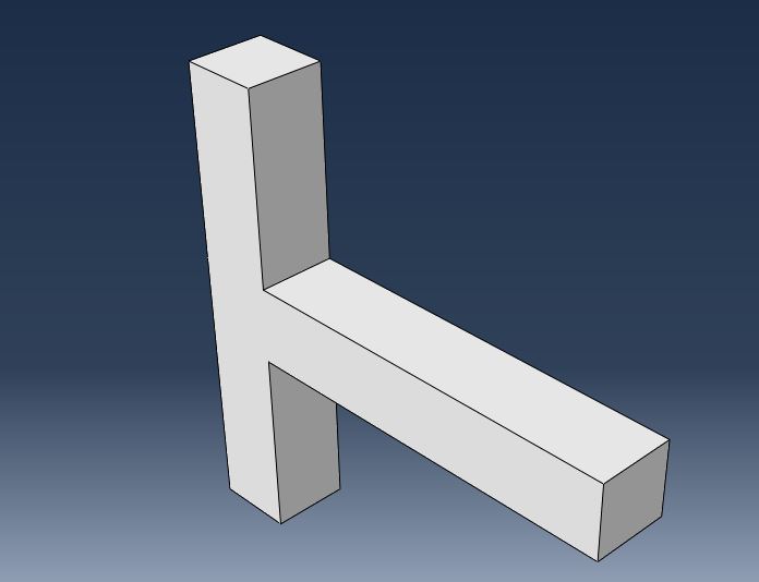
Figure 2: Software Material model
Model Dimensions
The nominal T-section dimensions in Figure 1 are a vertical extent of 300, a horizontal projection of 200 and a section thickness of 20 in the model geometry. The section form and its reinforcement determine how applied loads are transferred and how deformation develops. The nano-carbon cement concept is considered within this structural modelling framework, with ductility and load-bearing behaviour remaining central performance questions.
Material property
The T-beam shape has been carefully modeled as a finite element mesh to ensure a precise representation of its structural properties. This mesh combines solid and shell components, with the shell elements being particularly fine-tuned in the support areas to capture subtle behavior. Boundary static supports have been adequately imposed to imitate real-world circumstances, guaranteeing that the structural system’s reaction to external loads and limitations is successfully replicated, enabling thorough analysis and assessment.
Steel Material
Isotropic describes elastic properties, which means they behave mechanically the same way no matter which direction they are applied. The material’s stiffness is measured by the Young’s modulus, which is 210,000 units, and its lateral deformation under an axial force is described by the Poisson’s ratio, which is 0.3.
Mechanical properties | Symbol | Steel |
|---|---|---|
Youngs modulus (Gpa) | E | 205 |
Shear modulus (Gpa) | G | 75 |
Poission ratio | 0.3 | |
Density | 7500 | |
Yeild strength (Mpa) | 365 | |
Shear strength (Mpa) | 365 |
Table 1: Steel property
The yield stress, or point at which the material experiences permanent deformation, in the world of plasticity, is 250 units, and at this point, no plastic strain is visible. A plastic strain of 0.02 at a stress level of 346 units, however, indicates that the material is beginning to show plasticity as it continues to distort. These material characteristics are essential for engineering and design as they determine how the material will react to different loads and stresses.
Figure 3: Main steel |
Figure 4: Second Main steel |


Concrete and steel combining
Mainly because of its flexibility, the mechanical behavior may be described. Young’s modulus, a measurement of the material’s stiffness and capacity to withstand deformation under load, is defined at 21,000 units. This shows that the material is reasonably stiff and will only slightly distort when under load.
SI. No | Material Property | Values |
|---|---|---|
1 | Compressive strength of the concrete, | 28Mpa |
2 | Modulus of elasticity of concrete, | 24875 Mpa |
3 | Poison’s ratio of Concrete | 0.2 |
4 | Coefficient of Thermal expansion concrete | 9.9/0C |
5 | Shear modulus of concrete, | 10,365 Mpa |
6 | Yield stress of steel rebar | 420 Mpa |
7 | Tensile strength of steel rebar | 620 Mpa |
8 | Modulus of Elasticity of steel, | 200,000 Mpa |
9 | Poision ratio of steel, | 0.3 |
10 | Coefficient of thermal expansion of steel | 11.7/oC |
11 | Shear modulus of steel, | 76,920 Mpa |
The material’s capacity to expand laterally when crushed longitudinally is represented by the Poisson’s ratio, which has a value of 0.3. These characteristics are useful for structural analysis and other applications where mechanical behavior is an important factor because they provide crucial information on how the material will behave to various stresses and loads. They are basic to engineering and design.
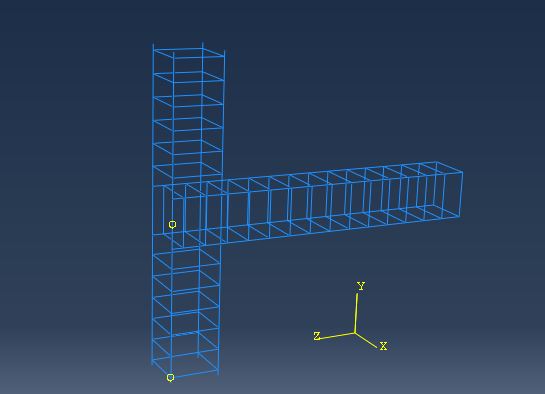
Figure 5: Steel blending with concrete
Assembly
Two steel components are conjugated and offset to produce a T-section, with the primary steel producing the vertical stem and the secondary steel forming the horizontal top portion. The primary steel is 200 meters long and acts as the vertical element of the structure’s support. On the other hand, the T-section’s horizontal flange, which extends 440 units horizontally from the stem, is made from the second steel, which measures 4 by 4 units. To increase the load-bearing capacity and structural integrity of beams or columns, this design is frequently utilized in building and engineering. The T-section shape is a flexible option for a variety of structural applications since it distributes and bears loads both vertically and horizontally well.
Load
The application of concrete forces to a structural system with precise boundary constraints is what is highlighted. U1, U2, U3, UR1, UR2, and UR3 are all set to zero during the establishment of BC-1 in order to guarantee that there is no displacement or rotation in any direction. The construction is effectively fixed in place as a result, with no rotation or movement allowed at that border. The vertical limitation is present in BC-2, on the other hand. The value of U2 is given as -100, denoting a downward displacement of 100 units, thereby simulating an external force acting on the structure in a downward direction. As they aid engineers in understanding how the structure will respond to certain loads, these boundary conditions and applied forces are crucial for structural analysis and design.
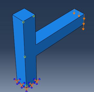
Figure 6: Load acting in T-Section
Meshing
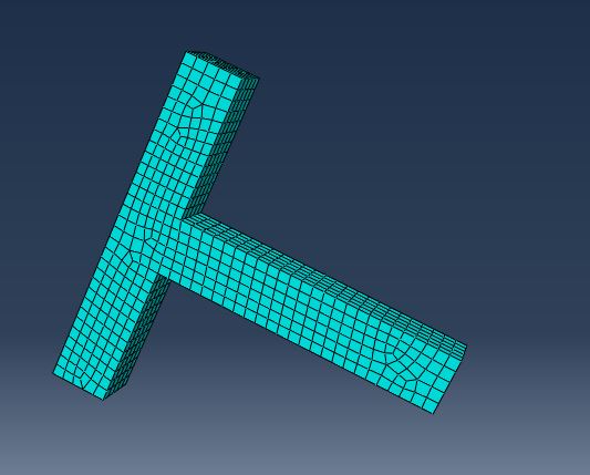
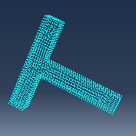
The technique of meshing involves breaking down a complicated geometries into more manageable, discrete parts, such as triangles or quadrilaterals for 2D issues or tetrahedra or hexahedra for 3D difficulties. Engineers and scientists can roughly predict the behavior of materials and structures under a variety of situations thanks to this meshing technique, which is essential in finite element analysis (FEA). For precise and effective simulations, the mesh quality and its associated parameters, such as the global size and the maximum deviation factor, are crucial.
The selection of mesh dimensions is crucial for T-sections made of cement with nanocarbon content. A global size of 100 denotes the assumption that the meshing elements are of a certain size, with smaller numbers denoting a finer mesh. The program may increase element size in parts with low geometric complexity while keeping a finer mesh in complicated regions, which can save computing resources, thanks to the maximum deviation factor of 0.1.
Figure 7: Mesh in shaded |
Figure 8: Mesh in wireframe |
Finite Element Modelling
Finite Element Modeling (FEM) is a flexible and strong numerical method used to study and resolve complicated issues based on physical phenomena in engineering, physics, and other scientific fields. With the use of finite element modeling (FEM), complex systems or structures may be successfully broken down into controllable, linked subdomains. These components act as the simulation’s building blocks, enabling the solution of complicated issues by the combination of simpler, interconnected parts. FEM is a key technique in the field of structural engineering for examining stress distributions, deformation patterns, and other important characteristics of mechanical systems. Using specialist software like Abaqus, which offers a platform for building, solving, and evaluating finite element models, FEM is often used in real-world engineering settings. The choice of relevant pieces to represent different structural aspects is a crucial component of this approach. The employment of Solid 202 components in the Abaqus instance is a noteworthy decision. For simulating how beams and columns interact in structural systems, these components are especially useful. In order to illustrate hard connections in three dimensions, Solid 202 components were chosen. The ability of these components to represent the structural behavior of connections in all three spatial directions the x, y, and z axes distinguishes them from other elements. This thorough technique guarantees that the simulation properly depicts the intricate relationships and load-bearing qualities that are inherent in structural components used in real-world structures. Particularly in three-dimensional space, it is crucial to take into account the complex interaction of forces, moments, and deformations when modeling connections between beams and columns. By offering a solid and trustworthy depiction of these behaviors, the Solid 202 components make this easier.
The accuracy and adaptability of FEM are demonstrated by the use of two Solid 202 components to join beams to columns. Engineers can explore localized impacts and interactions within the system while taking into account how they affect the system as a whole by using this method to divide the whole structural system into smaller, more manageable components. It allows for a greater knowledge of structural behavior and performance, making it a crucial component of the FEM technique.
To comprehend and evaluate how materials react under various loads and situations, these attributes are crucial. Allow us to dissect every one of these attributes:
Creep: When a material is exposed to a steady load or stress over a lengthy period of time, creep, a time-dependent deformation, develops in the material. During time, it can cause permanent deformation and is especially important for materials like metals and plastics.
Plasticity: The term “plasticity” describes a material’s capacity to deform permanently and irreversibly under applied loads that exceed a specific threshold without rupturing. Thermoplastics and metals are frequently seen to exhibit plastic deformation.
Deflection: The amount that a structural element, such a beam or a bridge, bends or sags when subjected to a load is known as deflection. Making ensuring a structure can resist the desired loads without suffering excessive deformation is crucial in structural engineering.
Swelling: When a substance absorbs a liquid, like water, its volume expands, causing swelling. In substances like wood, earth, and certain polymers, this is a typical occurrence. For several industrial operations as well as building, swelling can have substantial effects.
Stress Stiffness: Stress stiffness, often known as a material’s stiffness, is a measurement of how resistant a material is to deforming under an applied stress. In engineering, this basic feature is utilized to create components and structures. Higher stress stiffness materials are often more rigid and less malleable.
Strain: Strain is a unit of measurement for the deformation or shape change that a material experiences as a result of an applied force. The ratio of the size change to the material’s initial size is a common way to represent it. Understanding strain is crucial if one wants to comprehend how different pressures and loads affect materials.
Job analysis
Combining concrete and steel is a commonly used approach that produces buildings that take use of each material’s unique characteristics. Combining these two elements often results in the creation of a T-section, a structural element with increased stiffness and load-bearing capability. The first step in the analytical process is a comprehensive review of the input data, which forms the basis for evaluating the applicability and structural soundness of the T-section design.
Table 3: Monitor analysis in job components
Step | Increment | Att | Server discon iter | Equil iter | Total iter | Total Time/freq | Step Time/LPF |
|---|---|---|---|---|---|---|---|
1 | 1 | 1 | 0 | 2 | 2 | 0.01 | 0.01 |
1 | 2 | 1 | 0 | 1 | 1 | 0.02 | 0.02 |
1 | 3 | 1 | 0 | 1 | 1 | 0.035 | 0.035 |
1 | 4 | 1 | 0 | 1 | 1 | 0.0575 | 0.0575 |
1 | 5 | 1 | 0 | 1 | 1 | 0.09125 | 0.09125 |
1 | 6 | 1 | 0 | 1 | 1 | 0.141875 | 0.141875 |
1 | 7 | 1 | 0 | 1 | 1 | 0.217812 | 0.217812 |
1 | 8 | 1 | 0 | 1 | 1 | 0.331719 | 0.331719 |
1 | 9 | 1 | 0 | 2 | 2 | 0.502578 | 0.502578 |
1 | 10 | 1 | 0 | 3 | 3 | 0.758867 | 0.758867 |
1 | 11 | 1 | 0 | 2 | 2 | 1 | 1 |
During this crucial stage, the design must be carefully examined and monitored to make sure it complies with project specifications, technical principles, and safety regulations. To ensure the T-section is suitable for its intended use and strong enough to sustain expected loads, a number of parameters are carefully examined, including material qualities, applied loads, environmental influences, and architectural criteria. Engineers and architects make sure that the final T-section, which integrates the complementary qualities of steel and concrete, delivers a structurally sound and durable solution that complies with safety and performance expectations in the construction industry by carefully evaluating the input data and continuously validating the design throughout the project.
Results and Discussion
An innovative step forward in the search for materials resistant to earthquakes is the application of cement based on nano carbon. Because of its remarkable ductility, this novel cement formulation lowers the chance of structural collapse during earthquakes by allowing buildings to bend and absorb seismic energy. Buildings are better equipped to withstand seismic forces as a result of its outstanding performance, which also increases safety in areas where earthquakes are common.
Simulation analysis
There is hope for these novel materials in dwelling constructions as a result of the encouraging results of simulated testing on earthquake-resistant composites integrating high ductility nano carbon-based cement. When measured against conventional cement composites, the materials containing cement based on nanocarbons demonstrated much higher structural robustness. By effectively dispersing energy and lowering the danger of catastrophic collapse, these materials showed enhanced ductility during seismic simulations. The introduction of carbon nanoparticles, namely carbon nanotubes (CNTs), successfully stopped the cement matrix’s cracks from spreading. In the cement composites based on nanocarbon, this was demonstrated by the reduced fracture widths and fewer cases of crack branching. Improved tensile strength is essential for building homes in seismically active areas, and nanocarbon-based cement materials demonstrated this. As evidenced by their ability to withstand higher lateral and vertical stresses, these materials have the potential to improve structural integrity. The cement matrix’s carbon nanoparticles’ strong electrical conductivity made self-sensing possible. A potential use for early warning systems and structural health monitoring was made possible by the real-time data on structural deformation that was supplied by sensors placed in the cement composites based on nanocarbons during simulations.
The simulation test findings highlight the materials that are earthquake-resistant and incorporate high ductility nano carbon-based cement. Consistent with earlier research, these findings have great significance for the building sector, especially in areas susceptible to earthquakes. They also provide opportunities for more study and real-world implementation. When building a structure that is earthquake-resistant, the enhanced ductility shown in cement composites based on nanocarbons is essential. Due to this characteristic, there is a lower chance of an abrupt and disastrous collapse during seismic occurrences. Materials may absorb energy and deform. The effectiveness with which these materials can disperse energy is a crucial element in improving structural resilience.
Notable results include the reduction of fracture propagation inside the cement matrix. The addition of carbon nanoparticles, or CNTs, seems to strengthen the material in an efficient manner, preventing cracks from forming and enhancing its overall toughness. This is particularly helpful in earthquake-resistant housing, where reducing damage is essential. The findings are consistent with earlier research. For dwelling buildings in seismically active zones, nanocarbon-based cement materials’ increased tensile and flexural strength is essential. By withstanding the elevated stresses and deformations brought on by seismic activity, these materials enhance structural integrity and safety. An important development is the self-sensing ability made possible by carbon nanoparticles’ electrical conductivity. The ability to detect any problems early on facilitates timely maintenance and, in the case of an earthquake, may save lives and save money when structural deformation is monitored in real-time.
Stress in the T-Section
The stress contour in Figure 9 illustrates the distribution of von Mises stress in the T-section under the imposed loading. The displacement-magnitude contour in Figure 10 shows the corresponding deformation pattern. Together, these outputs describe where loading produces concentrated stress and larger displacement within the model. Such results can inform subsequent evaluation of structural response, although a loading simulation alone does not establish performance under a complete earthquake history.

Figure 9. Von Mises stress distribution in the T-section.
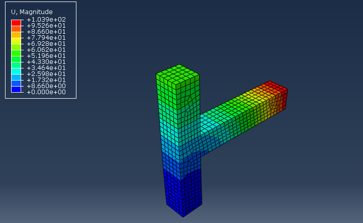
Figure 10. Displacement magnitude in the T-section.
Reaction Force Analysis
The RF contour reports reaction-force magnitude at constrained locations in the T-section model. The largest reactions occur around the fixed support, where the imposed constraints resist the applied loading. This output helps describe how forces are transferred through the assembly and complements the stress and displacement contours. RF is a mechanical reaction-force output in this analysis.
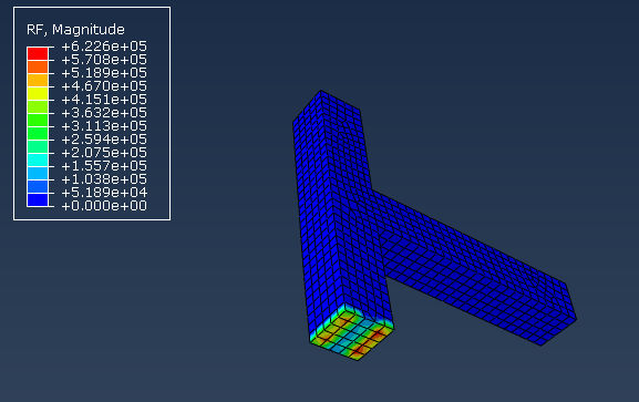
Figure 11. Reaction-force magnitude in the T-section.
Maximum Principal Plastic Strain
The PE contour reports maximum in-plane principal plastic strain in the T-section. Plastic strain describes irreversible deformation rather than stored potential energy. Its distribution helps identify regions where the material model develops permanent deformation under the specified loading. Interpreting this field alongside stress, displacement and support reactions provides a clearer account of the simulated structural response.
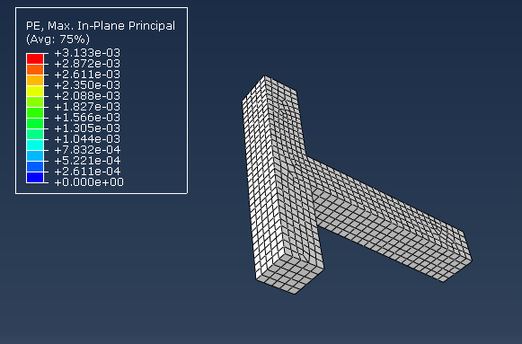
Figure 12. Maximum in-plane principal plastic strain in the T-section.
Conclusion
This study’s simulation experiments have shown how much potential there is to improve the seismic resistance of dwelling structures utilizing high ductility nano-based cement. Its special qualities greatly enhance the structural performance under seismic stress scenarios. Because of the extraordinary ductility of the cement based on nanotechnology, buildings can absorb seismic energy and deform without failing catastrophically. During earthquakes, the likelihood of brittle cracks and collapse can be reduced by this enhanced ductility. The mechanical characteristics of cement based on nanocarbon tubes were better understood thanks to this work. Investigations into complete material characterisation were completed satisfactorily. Knowing how it behaves under various loading scenarios is helpful. Together with environmentally friendly building practices, the viability of employing cement based on nanotechnology is taken into account. Subsequent investigations can expand upon this basis as earthquake-resistant technology advances. The material’s performance in various building scenarios and geographical locations requires validation through additional experimentation and field testing. This highly ductile cement material based on nanotechnology presents encouraging ways to lessen the destructive effects of earthquakes on residential buildings. Our quest for safer and more sustainable homes is still at the center of our efforts as we make more advancements in the field of seismic engineering.
References
Bensaude-Vincent, B., 2016. Building multidisciplinary research fields: The cases of materials science, nanotechnology and synthetic biology. The Local Configuration of New Research Fields: On Regional and National Diversity, pp.45-60.
Reales, O.A.M., Carisio, P.A., dos Santos, T.C., Pearl Jr, W.C. and Toledo Filho, R.D., 2021. Effect of pozzolanic micro and nanoparticles as secondary fillers in carbon nanotubes/cement composites. Construction and Building Materials, 281, p.122603.
Odermatt, R., Par, M., Mohn, D., Wiedemeier, D.B., Attin, T. and Tauböck, T.T., 2020. Bioactivity and physico-chemical properties of dental composites functionalized with nano-vs. micro-sized bioactive glass. Journal of clinical medicine, 9(3), p.772.
Wang, K., Liu, X., Tan, Y., Zhang, W., Zhang, S. and Li, J., 2019. Two-dimensional membrane and three-dimensional bulk aerogel materials via top-down wood nanotechnology for multibehavioral and reusable oil/water separation. Chemical Engineering Journal, 371, pp.769-780.
Slepička, P., Slepičková Kasálková, N., Siegel, J., Kolská, Z. and Švorčík, V., 2019. Methods of gold and silver nanoparticles preparation. Materials, 13(1), p.1.
Cui, K., Chang, J., Feo, L., Chow, C.L. and Lau, D., 2022. Developments and applications of carbon nanotube reinforced cement-based composites as functional building materials. Frontiers in Materials, 9, p.861646.
Gamal, H.A., El-Feky, M.S., Alharbi, Y.R., Abadel, A.A. and Kohail, M., 2021. Enhancement of the concrete durability with hybrid nano materials. Sustainability, 13(3), p.1373.
Kaur, R. and Kothiyal, N.C., 2019. Positive synergistic effect of superplasticizer stabilized graphene oxide and functionalized carbon nanotubes as a 3-D hybrid reinforcing phase on the mechanical properties and pore structure refinement of cement nanocomposites. Construction and Building Materials, 222, pp.358-370.
Narasimman, K., Jassam, T.M., Velayutham, T.S., Yaseer, M.M.M. and Ruzaimah, R., 2020. The synergic influence of carbon nanotube and nanosilica on the compressive strength of lightweight concrete. Journal of Building Engineering, 32, p.101719.
Naqi, A., Abbas, N., Zahra, N., Hussain, A. and Shabbir, S.Q., 2019. Effect of multi-walled carbon nanotubes (MWCNTs) on the strength development of cementitious materials. Journal of Materials Research and Technology, 8(1), pp.1203-1211.
Belbachir, A., Benanane, A., Ouazir, A., Harrat, Z.R., Hadzima-Nyarko, M., Radu, D., Işık, E., Louhibi, Z.S. and Amziane, S., 2023. Enhancing the Seismic Response of Residential RC Buildings with an Innovative Base Isolation Technique. Sustainability, 15(15), p.11624.
Jirimali, H., Singh, J., Boddula, R., Lee, J.K. and Singh, V., 2022. Nano-Structured Carbon: Its Synthesis from Renewable Agricultural Sources and Important Applications. Materials, 15(11), p.3969.
Zhang, L., Ji, Y., Li, J., Gao, F. and Huang, G., 2019. Effect of retarders on the early hydration and mechanical properties of reactivated cementitious material. Construction and Building Materials, 212, pp.192-201.
Kim, G.M., Nam, I.W., Yang, B., Yoon, H.N., Lee, H.K. and Park, S., 2019. Carbon nanotube (CNT) incorporated cementitious composites for functional construction materials: The state of the art. Composite Structures, 227, p.111244.
Du, M., Jing, H., Gao, Y., Su, H. and Fang, H., 2020. Carbon nanomaterials enhanced cement-based composites: advances and challenges. Nanotechnology, 9(1), pp.115-135.
Huq, M.S., Burgos, E.A., Lequesne, R.D. and Lepage, A., 2021. High-Strength Steel Bars in Earthquake-Resistant Reinforced Concrete T-Shaped Walls. American Concrete Institute.
Silva, L.M., Vasconcelos, G. and Lourenço, P.B., 2021. Innovative systems for earthquake-resistant masonry infill walls: Characterization of materials and masonry assemblages. Journal of Building Engineering, 39, p.102195.
Papavasileiou, G.S. and Charmpis, D.C., 2020. Earthquake-resistant buildings with steel or composite columns: Comparative assessment using structural optimization. Journal of Building Engineering, 27, p.100988.
Samuel, J., Nair, S.R., Joanna, P.S., Gurupatham, B.G.A., Roy, K. and Lim, J.B.P., 2023. Composite Cold-Formed Steel Beams with Diagonal Rebars for Earthquake-Resistant Buildings. Materials, 16(8), p.3002.
Rong, Z., Yu, X., Xu, B. and Du, X., 2021. Reliability analysis of high concrete-face rockfill dams and study of seismic performance of earthquake-resistant measures based on stochastic dynamic analysis. Mathematics, 9(23), p.3124.
de Salles, H.B., Miguel, L.F.F., Lenzi, M.S., Lopez, R.H. and Beck, A.T., 2023. A Fast Frequency Sweep approach for performance-based optimization of earthquake-resistant irregular large-scale buildings. Engineering Structures, 285, p.116094.
Nady, O., Mahfouz, S.Y. and Taher, S.E.D.F., 2022. Quantification of Vertical Irregularities for Earthquake Resistant Reinforced Concrete Buildings. Buildings, 12(8), p.1160.
Sarcheshmehpour, M. and Estekanchi, H.E., 2021, April. Life cycle cost optimization of earthquake-resistant steel framed tube tall buildings. In Structures (Vol. 30, pp. 585-601). Elsevier.
Rahmi, S., Aisya, R. and Amelya, M., 2023. The Use of Lightweight Bricks in Earthquake-Resistant House Construction in Mentawai. International Journal of Ethnoscience, Bio-Informatic, Innovation, Invention and Techno-Science, 2(01), pp.67-72.
Bamanikar, M.A. and Khurd, V.G., 2021. Non-Linear Dynamic Analysis of Earthquake Resistant Reinforced Concrete Building.
Cite This Work
To export a reference to this article please select a referencing stye below:

Academic Master Education Team is a group of academic editors and subject specialists responsible for producing structured, research-backed essays across multiple disciplines. Each article is developed following Academic Master’s Editorial Policy and supported by credible academic references. The team ensures clarity, citation accuracy, and adherence to ethical academic writing standards
Content reviewed under Academic Master Editorial Policy.