Introduction
The recent advancements in the fields of Materials Science and all its sub-fields have revolutionized the world. State-of-the-art technological progressions in all domains of materials including metals, ceramics, and polymers are evident due to the evolution of large-scale, heavy-duty machinery into Nano-sized and Pico-sized devices. The polymers, in general, have benefitted hugely from such innovations. The amalgam of different materials for the purpose of strengthening a structure referred to as composites, have also enhanced the horizons of structural and industrial materials. Two or more component materials combine to enhance physical or chemical characteristics of a material in the form of a composite. The reinforcing substances are embedded as additives into the matrix material, which provides robustness and strength to the material without chemical bonding between the ingredient materials. In the process, some of the properties of the constituent materials have to be compromised as well.
Composites can be largely classified according to the dimensions of the ingredients as particle reinforced composites, fiber reinforced composites, and structural composites. Out of these, fiber-reinforced composites are the most advanced. Composites are extant naturally in the form of woody plants that contain gluey resins and hard wood. Artificial fabrication techniques soon adopted these natural patterns by incorporating plywood, concrete, papier-mâché, and glass into the construction industry.
Polymer-Matrix Composites (PMCs)
Polymer-matrix composites are a sub-type of fiber-reinforced composites in which several functions are performed by the matrix phase. The paramount function of binding the fibers is performed by the matrix along with facilitating the distribution of the externally applied stress throughout the fibers. The matrix also provides protection to the fibers from the external environment degradation in the form of chemical reactions and mechanical abrasion (Allegra et. al., 2008).
Polymer Matrix Composites constitutes of a matrix, for which resins are mostly employed, and reinforcement medium, for which fibers are incorporated into the structure. Resins are high molecular weight plastics. PMCs are known for their utility and applicability in diverse setups and installations, light weight properties, excellent room-temperature characteristics, cost effectiveness, and ease of fabrication (Kumar et. al., 2010). PMCs are broadly classified in accordance with their reinforcement medium as Glass Fiber-Reinforced Polymer Composites (GFRP), Carbon Fiber-Reinforced Polymer Composites (CFRP), and Aramid Fiber-Reinforced Polymer Composites. Each has z unique set of functionality and properties that have furthered the successes of the field (Moniruzzaman et. al., 2006).
Carbon Fiber-Reinforced Polymer Composites (CFRP)
Carbon is employed as an underlining agent in the polymer-matrix composites due to its high performance. The functionality of carbon is enhanced by its specific modulus and specific strength, which is the highest among the large cohort of reinforcing agents available. The retention of high tensile modulus under stress and exhibition of excessive strength at raised temperatures add to the versatility of the material. Elevated temperatures, however, cause oxidation of the carbon bonds that degrades the suitability of the specimen in heated environments. The lack of reactivity or absorption of moisture at standard temperature and pressure conditions, along with multifarious solvents, bases, and acids from the milieu adds to the dynamics of the carbon fibers. Furthermore, the fabrication processes are time and cost efficient, which makes carbon fibers an excellent asset for a wide range of purposes (Bal et. al., 2007).
The fibers of Carbon are not entirely crystalline in appearance but contain streaks of both non-crystalline areas and graphitic structure, which makes carbon fibers partly crystalline. The three-dimensionally arranged arrays of six-sided carbon networks impart non-crystallinity to the structure of carbon fibers unlike that of graphite. The organic precursors used in the fabrication processes of carbon fibers include pitch, rayon, and polyacrylonitrile (PAN). The methodology of manufacturing varies according to the precursor used.
The categorization of carbon fibers can be done according to tensile modulus, which yields four subcategories of the material tantamount to standard, intermediate, high strength, and ultra high modulus carbon fibers. Apparently, the features of carbon fibers can be distinguished by their diameters that lie in the range of 4 to 10 micrometers. Moreover, the fibers of carbon are available in continuous bundles as well as chopped forms. For the protection of the fibers, they are coated with a protective layer of epoxy that imparts adhesive properties as well when employed with the polymer matrix (Tjong, 2006).
The general applications of CFRPs can be found in industries of sports and recreational equipment manufacturing where they are exploited for making golf clubs and fishing rods. They are also incorporated into filament-wound rocket motor cases, pressure vessels, military and commercial airplane structural parts, helicopters, fixed wings, cycling bodies, fast boats and ships, and the likes. Carbon fibers have also found their usability in the space industry where the floors of space shuttles have been constructed from the material, which provides strength and durability at the same time (Allegra et. al., 2008).
Carbon Nanotubes (CNTs)
CNTs were manufactured in the laboratory for the first time by Professor Iijima in the year 1991 and were debuted into the polymer Nano-composites as fillers in the year 1994 by Ajayan et. al. (1994). Previously carbon fibers utilized in Nano-composites were made of carbon blacks, clays, silica, and Nano-fibers that imparted thermal, electrical, and mechanical characteristics to the composites in the desired quantities.
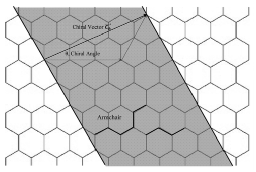
Figure 1 – Schematic of Graphene Sheet
CNTs are covalently bonded atoms of carbon that are in the shape of long cylinders. Hemi-fullerenes are sometimes also present at the ends of the CNTs (Coleman et. al., 2006). The basic division among CNTs can be achieved by categorizing them into Single Walled Carbon Nanotubes (SWNTs) and Multiwall Carbon Nanotubes (MWNTs). SWNTs consist of single sheets of sp2-bonded graphene that is rolled in the form of a seamless cylinder. Due to the curvature provided by the cylinder to the carbon atoms they are changed into sp3 bonds. MWNTs, on the other hand, comprises of nested graphene cylinders that are arranged in a coaxial manner around a centrally hollowed core having a separation between layers of 0.34 nanometers, which makes it’s a sub-type of graphite (Tjong, 2006).
Special types of MWNTs also exist that are referred to as double-walled nanotubes (DWNTs) as they are made of two concentric cylinders of graphene. Unique properties are sometimes included in the CNTs due to an inclusion of foreign particles or C60 molecules, which adds additional transportation facilitation to the material (Coleman et. al., 2006).
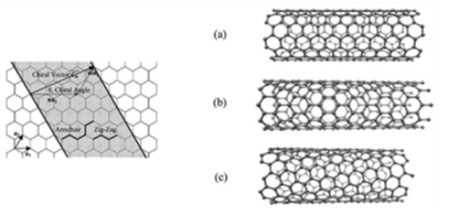
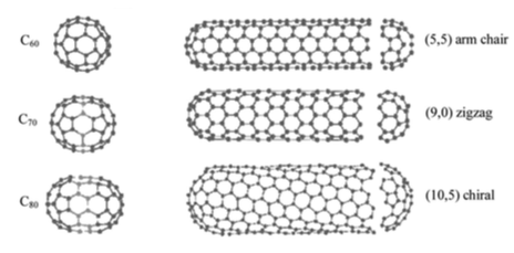
CNTs also have three unique chiralities depending upon the rolling angle of the graphene sheet employed tantamount to the armchair, zigzag, and chiral spatial features. The chiral vector Ch = na1 + ma2 is responsible for the chirality of the tube. The integers n and m gives the quantity of steps along unit vectors a1 and a2 in the hexagonal lattice structure. On the basis of this scheme, n and m values decide the orientations around the circumference of the nanotubes of carbon. Armchair configuration is attained when n and m are equal. A zigzag formation is attained in the case when m is equal to zero. When n is equal to zero, the configuration acquired is chiral in nature. Chirality of the CNTs affects the transport properties especially electronic in nature (Moniruzzaman et. al., 2008)
Figure 2 Schematic of Hexagonal Graphene Sheet rolled into CNT Chiralities: a – armchair, b – zigzag, c – chiral
The fabrication of CNTs is mostly achieved by chemical or vapor deposition procedures. Variations in surface alignments and orientations of the reinforcements make the distribution more homogeneous having little agglomeration. It also imparts enhanced interfacial bonding to the fillers and the matrix. Oxidation, functionalization, and usage of surfactants are common in the fabrication of CNTs (Camargo et. al., 2009).
The chemical methods of manufacturing are generally more effective especially for ceramics and polymers as matrix materials. In-situ polymerization and physical blending has the advantage of boosting the dispersion for CNT reinforced composites having polymer matrix. However, better alignment is achieved by ex-situ procedures of plasma enhanced chemical vapor deposition, filtration, and force field inducements (Camargo et. al., 2009).
From Graphene Sheet to Single Walled Nanotubes
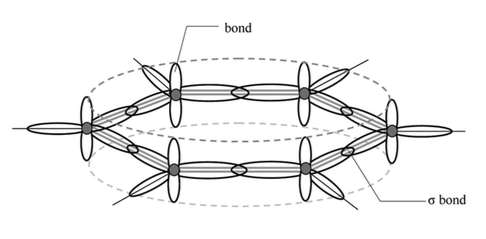
CNT can be thought of as a rolled sheet of graphene, each of which has a specific direction and circumference along the cross-section. Figure 2 shows a typical graphene sheet that is rolled up and defined according to the roll-up vector known as r. The rolling leads to the formation of a nanotube, the ends of which coincide. Here the delocalized line represents the out-of-plane bonds, and sigma bonds connect in-plane bonds to carbon.
Figure 3: Hexagonal bonding for graphene sheet with carbon nuclei
R = na + mb
R gives the linear combination of base vectors a and b, which also gives an idea about the chirality of the CNT.
Figure 4 – Chiralities and Ending Fullerenes
Properties of CNTs
The distinguishing capabilities of CNTs which set them apart from the cohort of other Nano-fibers is their intense flexibility, large aspect ratio ranging between 300 and 1000, and low mass density. The up-gradation to mechanical, thermal, and electrical dynamics yielded by carbon Nano-fillers takes them to unprecedented levels of excellence for employment into multifunctional polymer Nano-composites. A certain kind of CNT is even sturdier than steel, lighter than aluminum, and more conductive than copper.
Theoretical and experimental results have revealed the tensile modulus of single-walled CNTs known as SWNTs to be in the range of 640 GPa and 1 TPa. Further versatility is added to SWNTs by their structural availability according to the parameters, in the form of either metallic or semiconducting materials. As the SWNTs are one-dimensional in their spatiality so they have electronic structures that can support and transmit electrons over large distances with minute scattering, as the mean free path of SWNTs is recorded to be several microns. SWNTs also demonstrate large phonon mean paths, which adds to their thermal conductivity properties reaching up to 6000 W/mK.
As the technology is relatively new in the market, it is not yet commercially accepted into products. The main reason for this is the inconsistent nature of CNTs due to the inclusion of impurities and defects. There are a wide variety of impurities and defects even within the same batch of CNTs. The inability to reproduce controlled specimens hinders the material to reach its destined heights of success and usability commercially.
Characterization of CNTs
Inadequate techniques of characterization according to direct measurement of properties, immense restrictions on the size of the specimen, uncertainty due to indirect acquisition of data, uncontrollable alignment, orientation, and distribution of nanotubes, and incompetent sample preparation methodologies are some of the challenges faced during the process of categorization of CNTs.
Mechanics of Single-Walled Carbon Nanotubes
Reinforcements for PMCs are either isodimensional or two-dimensional. CNTs are two-dimensional elongated structures. It is found that the tensile strength and Young’s modulus increases with good adhesion of the oxidized carbon fibres, whereas an increase of the volume fraction of the fibres led to a decrease in the stiffness. The strength and torsional modulus of the Single Walled Carbon Nanotubes in Polymer matrixes was higher than that of PEEK matrix. The Young’s modulus for SWCNT is between 2.8 – 3.6 TPa, whereas fifteen or more bundles of the fibers underwent and sustained a load of 1002 GPa (Qian et. al., 2002).
Several scientists have investigated the theoretical and experimental values of mechanics associated with SWNTs. The low-frequency vibrational modes along with structural rigidity of CNTs was studied by Overney et. al. (1993), who founded their study on the basis of Keating Hamiltonian empirical formulas and parameters. He also presented a contrasting study of bending stiffness between an iridium beam and SWNT. The Bernoulli-Euler theory of bending the beam was exploited for deduction of the stiffness for the iridium beam. It was concluded that the beam bending capabilities of SWNTs exceeds any other material available.
Iijima et. al. (1996), observed the reaction of CNTs under stress via molecular dynamics simulations, which was achieved at large angles for SWNTs. It was revealed that SWNTs are extraordinarily flexible. The deformation led to the creation of intricate kinks and bends in the SWNTs, yet the bends were reversed up till the limiting angles of 110o. Ru et. al. (2000), however, found that the bending stiffness is much less than that proposed by the elastic-continuum shell model if the representative thickness is taken into account. He and his associates proposed the employment of the stiffness factor in relation to the material rather than the thickness of the material. The equations can be modified according to this concept that engenders computational results for the SWNTs.
Chirality and structure of nanotubes also influence the tension, bending, and torsion of the material according to the investigations conducted by Vaccarini and his associates. Chirality does not affect tensile modulus of the CNTs but adds torsional behavior to chiral form (Vaccarini et. al., 2000). To calculate the phonon spectrum and elastic features of CNTs. Lu and his fellows relied on the lattice dynamics model, which approximates the volume of atomic interactions taking place in a layer of carbon atoms via pair-wise harmonic potentials. Conformal mapping is then used to manufacture a cylindrical sheet of graphene. His work included aspects of size and shape (Lu, 1997).
It was concluded that are elastic features are independent of size and chirality. The Young’s modulus was found to be nearly 1 TPa, whereas the value of bulk modulus was 0.74 TPa, and that of shear modulus came to be nearly 0.45 TPa. These values are comparable to that of the diamond. Yarkobson et. al. (2000) has investigated to find the instability beyond linear reactions of the CNTs via realistic Tersoff- Brenner potential and MD simulations. It has revealed that stress deforms the CNTs into reversible morphologies to release energy. They also provided a guideline according to the parameters altered.
SWNTs formed via processes of laser ablation and techniques of arc-discharge have higher tendency to align themselves into ropes or bundles. A modified version of the elastic-honeycomb model was implemented to examine the buckling of CNT ropes under high stresses. The formula for evaluating critical values of pressure in relation to Young’s modulus as well as the wall thickness to radius ratio was presented by Ru in his research. He concluded that SWNT ropes are prone to buckling that induces deformations in the vibrational modes along with the resistivity of SWNTs.
CNT Composites
The integrity of Nano-composites is dependent on the ability to disperse uniformly in the matrix of polymer, enhanced wetting of the tubes, and perfect adhesion. Salvetat et. al. (1999) worked on finding the mechanism of slipping when the tubes are arranged in the form of ropes, which are unbounded in the matrix. The aggregation of such ropes minimizes the aspect ratio of the filler material.
Shaffer and Windle obtained CNT polyvinyl alcohol films to find damping and elastic properties via dynamic mechanical thermal analyzer (DMTA), with loading and temperature as the variables. For short fibers, 150 MPa was determined as the elastic modulus. This value contradicts with the high values of other CNTs due to unknown reasons, which have been attributed to imperfect catalytic growth or immense rate of stress transfer.
Polystyrene composites comprising of CNTs were formulated by Qian et. al. (2002), which revealed that with an addition of 1% weight, an enhancement of 36 – 42 % was observed for elastic stiffness, whereas tensile strength experienced a boost of 25 %. In another method, AIBN initiator was utilized to initiate a free-radical formation of CNTs within a matrix of Poly Methylmethacrylate (PMMA) (Jia et. al., 1999). The surfactant-assisted process of fabrication was also brought into use, which resulted in enhanced dispersion along with better interfacial bonding properties between epoxy that, in turn, yielded a 30 % increase in elastic modulus.
The method of Raman Spectroscopy has also been exploited to investigate the behavior of CNTs under stress and how it is propagated throughout the material. A composite sample prepared by application of epoxy resin to the surface of a beam after which it was cured, generated by Cooper et. al. (2001). The G. Raman band of 2610/cm was employed to study the factors, which was revealed by shifts in the bands. The effective modulus obtained via this technique for SWNTs was approximately 1 TPa, which is much higher than that for MWNTs (Cooper et. al., 2001 ).
An approximately constant value for tension in the Raman peak indicates a tube sliding with the bundles and ropes, which, in turn, is indicative of weak interfacial transfer load between the CNTs. (Ajayen et. al., 1999). Due to the random distribution of tubes, dispersion and adhesion is a tiresome task to achieve. Mechanical stretching of the composite helps in acquiring alignment of the CNTs (Jin et. al., ), which is facilitated by X-ray diffraction. Another technique was to melt spin the SWNTs into fibers that a well-aligned within the CNTs. (Haggenmueller et. al, 2000)
Modeling and Simulation of CNTs
Up till the recent era of technological advancements, all examinations into the behavior study of CNTs has been based on molecular dynamics simulations including tight-binding molecular dynamics, classical molecular dynamics, and AB initio method. Other researchers have explored the continuum shell ideal to understand the phenomenon of buckling via atomic molecular-dynamics simulations. (Yakobson et. al., 1996). Similarly, Ru and his associates to stimulate a Vander Waal force, which strengthens the evidence in support of continuum shell model application, applied the computational mechanic’s approach (Ru, 2001). Yiao and Han discussed the post-buckling torsional behavior of CNTs under compression or expansion for SWNTs.
Methods of Scaling
Atoms, molecules, and clusters of molecules are taken as the basic units to be studied via modeling and simulation methodology at a molecular scale. It is mainly aimed at comprehension of kinetics and thermodynamics of the CNTs, their interaction patterns, and molecular structures. Molecular mechanics has been employed in the form of Molecular Dynamics (MD) and Monte Carlo (MC) for the purpose.
Molecular Dynamics
The computational technique to predict the evolution time span of a particular system consisting of interacting agents along with associated physical properties is known as molecular dynamics. It provides information about the positions of atoms, their velocities and other macroscopic features such as heat capacity, energy, and pressure. A particular simulation of MD particularly consists of three ingredients:
- Initial conditions of positions and velocities
- Representation of forces existing between particles via interaction potentials.
- A solution of traditional Newtonian equations providing data about the evolution of a system in time.
The equation for motion is given by
The term Fi(t) indicates the force that is acting on the ith atom at a time t. F is acquired as the negative gradient of interaction potential U. Mi is the atomic mass whereas ri is the atomic position.
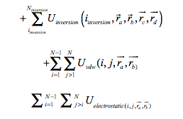
A thorough simulation involves the appropriate choice of interactive potentials, regulation of temperature and pressure, numerical integration, and boundary condition establishment. The force field is obtained through quantum method (AB initio), empirical method (Born-Mayer method), or a combination of quantum and empirical method (embedded atom model). The interaction potential comprises of several terms that embody factors of bonded and nonbonded interactions.
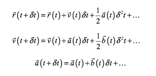
The system takes into account the values of bonds, angles, torsion, and inversion experienced by the bonded and non-bonded atoms. Several algorithms for integration of motion equations through finite difference methods also exist. Some examples include the leapfrog and Beeman model, velocity varlet, and varlet algorithms. All these systems consider Taylor series in action for finding r, v, and a.
Advantages of the MD method include performance in various ensembles such as the canonical (NVT), micro canonical (NVE), isothermal-isobaric (NPT), and grand canonical (micro VT). MD can be regulated through thermostats and pressure via barostat. The application of MD in polymer composites opens the chance to explore the influence of fillers on the dynamics of polymer-matrix composites.
Monte Carlo
The technique is also known as Metropolis method. The process is stochastic in nature because it employs random integers to produce a population of samples for the system through which the desired properties can be calculated. The process comprises of three constituent steps.
- The problem under examination is translated into a probabilistic model.
- The statistical model is solved via numerical sampling of the experiment.
- The third step involves analysis of the data obtained through models of statistics.
The restriction of MC is that it provides an analysis of the equilibrium characteristics only such as phase equilibrium and free energy. MD, on the other hand, works in conditions of non-equilibrium. For NVT conditions, containing N atoms, the configuration can be formed by moving atoms from one place to the other i.e. from i to j. The atomic movement causes a change in the Hamiltonian system, which is given as below.
I and J are the locations of the new configurations.
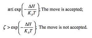
In cases where the change in H is less than zero, the system is lowered to a new energy, which is readily accepted by the system. When the change is positive, the movement is accepted within limited a probability that is given below.
K is the Boltzmann constant.
A random number can be generated for determination of the new configuration according to the following set of rules (Metropolis et. al., 2004)
In the case of rejection, the original position is also counted as the new position.
The advantage of this method is that it can be utilized to examine the molecular structure and configuration at Nano-particulate surfaces along with the influences of multifarious factors on the surface.
Micro Scale Methods
Brownian Dynamics (BD)
It is similar to Molecular Dynamics, but its difference is that it considers approximate values, which permits the function of simulations on microsecond timeline, whereas for MD setups can go up to nanoseconds. It uses an explicit description of solvents as compared to MD that uses implicit continuum description of the solvent. These features make BD useful in systems where large gaps exist for governance of motion of various components. It takes into consideration the Langevin equation for equating various factors (Mahmoodi et. al., 2017).
The equation takes the conservative forces acting on particles into consideration along with momentum, Gaussian noise factor, and other constants. The disadvantage of the technique is that it can only reproduce diffusion characteristics and not the features of hydrodynamic flow as the modeling method do not follow the equations and principles of Navier-Stokes Law.
Dissipative Particle Dynamics (DPD)
The process was fabricated by Koelman and Hoogerbrugge, which can model Newtonian and non-Newtonian fluids as well. It can also simulate polymer melts and blends at micro-scale. DPD is based on particles like BD and MD, but it relies on an assembly of molecules. Mi defines the mass of DPD particles, ri is the position, Pi is the momentum. The contact between particles I and j can be equated with the help of conservative, dissipative, and random forces as below.
The interaction potentials of DPD are softened to approximate values. The conservative force is chosen to minimize along with increasing position r. DPD incorporates Navier- Stokes law as the forces act in pairs and conservation of momentum is ensured. Due to the dissipation of energy through random forces, energy cannot be conserved in the system. In this respect, it resembles BD (Mahmoodi et. al, 2017).
The mechanism has multifarious benefits over MD technique such as hydrodynamic flow in case of fewer particles as compared to MD simulation. Moreover, it also permits greater time intervals due to its different force forms to be instilled in the system as compared to the MD.
Lattice Boltzmann
Effective treatment of polymers can also be accomplished by Lattice Boltzmann (LB) technique, which has also been employed in the investigation of phase separation experienced by binary fluids. Its origins can be found in the lattice gas automation process, which takes all values of velocities, space, and time in a discrete manner. LB has aimed at replacement of Boolean variables with real variables through distribution functions of single-particles along with the elimination of motion of the individual particles (Mahmoodi et. al., 2017).
LB has the benefit of assimilation of physical interactions in the fluid into the statistical model. It can also handle the fluid particle integrations along with the reproduction of the hydrodynamic behavior. In nature and working, LB resembles MD. It goes a step further to bridge the gap between microscopic and macroscopic scales. Its disadvantage lies in its inability to guarantee numerical stability, which might create unreliable results.
Time Dependent Ginzburg-Landau Method (TDGL)
It is mostly used in cases of polymer blends and block copolymers that require timeline of the evolution of their phase-separation. The technique is founded on the Cahn-Hilliard-Cook (CHC) diffusion technique that is used in binary blends. The mechanism requires the reduction of the free-energy function for the simulation of a temperature quenches from a miscible region to an immiscible region on the phase diagram. The relation obtained can be solved for finding the mutual interaction between the concentration of the blend and time (Glotzer et. al., 1999).
The chief benefit of the technique is that it can reproduce the growth kinetics, which can lead to the precise form of potentials that are free form the invasions of the free-energy terms.
Dynamic DFT Method
This model combines the Gaussian average-field statistics with TDGL standards for simulation of the evolution of various parameters. The benefit of this method is that truncation of free-energy does not take place as compared to the TDGL method as this yields a much more specific and detailed examination of the polymer system. Another benefit of the method is the ability to find the viscoelasticity that is not possible in the TDGL model. Doi et. al. (2001), has developed a similar approach to new simulation software known as Simulation Utility for Soft and Hard Interfaces (SUSHI).
The essence of the DFT method lies in the ability to instantly conform unique distribution patterns through non-equilibrium density profiles to the help of artificial external potentials. The free energy distribution is then calculated by the statistical thermodynamics.
Conclusion
Several other mesoscale and macroscale methods of simulation and modeling also exist that can be used for other purposes. However, the best modeling methods are MD and MC, which has a vast range of applications. The progressions in the field are non-stop.
Reference:
Overney, G., Zhong, W., & Tomanek, D. (1993). Structural Rigidity and Low-Frequency Vibrational Modes of Long Carbon Tubules, Zeitschrift Für Physik D Atoms, Molecules and Clusters, 27(1), 93–96.
Iijima, S. et al. (1996). Structural Flexibility of Carbon Nanotubes, The Journal of Chemical Physics, 104(5), 2089–2092
Vaccarini, L. et al. (2000). Mechanical and Electronic Properties of Carbon and Boron-Nitride Nanotubes, Carbon, 38(11), 1681–1690.
Ru, C. (2000). Effective Bending Stiffness of Carbon Nanotubes, Physical Review B, 62(15), 9973.
Iijima,S. (1991) .HelicalMicrotubulesofGraphiticCarbon,Nature,354(6348),56–58.
Iijima, S. (1993). The Growth of Carbon Nanotubes, Materials Science and Engineering B, 19(1), 172–180.
Yakobson, B., Samsonidze, G., & Samsonidze, G. (2000). Atomistic Theory of Mechanical Relaxation in Fullerene Nanotubes, Carbon, 38(11), 1675–1680.
Journet, C. et al. (1997). Large-Scale Production Of Single-Walled Carbon Nanotubes by the Electric-Arc Technique, Nature, 388(6644), 756–758
Thess, A. et al. (1996). Crystalline Ropes of Metallic Carbon Nanotubes, Science-AAAS-Weekly Paper Edition, 273(5274), 483–487
Ru, C. (2000). Elastic Buckling of Single-Walled Carbon Nanotube Ropes Under High Pressure, Physical Review B, 62(15), 10405
Ajayan, P., Schadler, L., & Braun, P. (2006). Nanocomposite Science and Technology, John Wiley & Sons, 550.
Ajayan, P. et al. (1994). Aligned Carbon Nanotube Arrays Formed by Cutting a Polymer Resin-Nanotube Composite, Science, 265(5176), 1212–1214.
Ru, C. (2000). Effect of van der Waals Forces on Axial Buckling of a Double-Walled Carbon Nanotube, Journal of Applied Physics, 87(10), 7227–7231.
Ru, C. (2001). Axially Compressed Buckling of a Double-walled Carbon Nanotube Embedded in an Elastic Medium, Journal of the Mechanics and Physics of Solids, 49(6), 1265–1279.
Jia, Z. et al. (1999). Study on Poly (Methyl Methacrylate)/Carbon Nanotube Composites, Materials Science and Engineering A, 271(1), 395–400.
Tjong, S.C., Structural and Mechanical Properties of Polymer Nanocomposites, Materials Science and Engineering, R 54 (2006) 73 – 197
Ajayan, P. et al. (2000). Single-Walled Carbon Nanotube–Polymer Composites Strength and Weakness, Advanced Materials, 12(10), 750–753
Moniruzzaman, M., Winey, K.I., Polymer Nano-composites Containing Carbon Nanotubes, Macromolecules, 2006, 39, 5194 – 5205
Allegra, G., Raos, G., Vacatello, M., Theories and Simulations of Polymer-based Nano-composites: From Chain Statistics to Reinforcements, Progress in Polymer Science, 2008, 33: 683 – 731
Salvetat, J., et al. (1999). Elastic and Shear Moduli of Single-Walled Carbon Nanotube Ropes, Physical Review Letters, 82(5), 944.
Qian, D., et al. (2002). Mechanics of Carbon Nanotubes, Applied Mechanics Reviews, 55(6), 495–533.
Shaffer, M., & Windle, A. (1999). Fabrication and Characterization of Carbon Nano- tube/Poly (Vinyl Alcohol) Composites, Advanced Materials, 11(11), 937–941.
Cooper, C., Young, R., & Halsall, M. (2001). The Investigation into the Deformation of Carbon Nanotubes and Their Composites Through the Use of Raman spectroscopy, Composites Part A Applied Science and Manufacturing, 32(3), 401–411
Haggenmueller, R. et al. (2000). Aligned Single-Wall Carbon Nanotubes in Composites by Melt Processing Methods, Chemical Physics Letters, 330(3), 219–225.
Yakobson, B., Brabec, C., & Bernholc, J. (1996). Nanomechanics of Carbon Tubes Instabilities Beyond Linear Response, Physical Review Letters, 76(14), 2511–2514
Morita, H., Kawakatsu, T., & Doi, M. (2001). Dynamic Density Functional Study on the Structure of Thin Polymer Blend Films with a Free Surface, Macromolecules, 34(25), 8777–8783
Hoogerbrugge, P., & Koelman, J. (1992). Simulating Microscopic Hydrodynamic Phenomena with Dissipative Particle Dynamics, EPL (Europhysics Letters), 19(3), 155
Metropolis, N. et al. (2004). Equation of State Calculations by Fast Computing Ma- chines, The Journal of Chemical Physics, 21(6), 1087–1092
Coleman, J.N., et al., Small but strong: A review of the mechanical properties of carbon nanotube–polymer composites. Carbon, 2006. 44(9): p. 1624-1652.
Bal, S. and S.S. Samal, Carbon nanotube reinforced polymer composites—A state of the art. Bulletin of Materials Science, 2007. 30(4): p. 379-386.
Kumar, S.K. and R. Krishnamoorti, Nanocomposites: Structure, Phase Behavior, and Properties. Annual Review of Chemical and Biomolecular Engineering, 2010. 1(1): p. 37-58.
Mahmoodi, M.J. and M. Vakilifard, A comprehensive micromechanical modeling of electro-thermo-mechanical behaviors of CNT reinforced smart nanocomposites. Materials & Design, 2017. 122: p. 347-365
Camargo, Pedro Henrique Cury, Satyanarayana, Kestur Gundappa, & Wypych, Fernando. (2009). Nanocomposites: synthesis, structure, properties and new application opportunities. Materials Research, 12(1), 1-39. https://dx.doi.org/10.1590/S1516-14392009000100002


