
Abstract
Stroke can affect arm function and the ability to perform activities of daily living (ADLs). This engineering study presents an upper-limb exoskeleton integrated with virtual reality for tracing and training everyday movements. The design covers five joint movements: shoulder flexion and extension, shoulder vertical abduction and adduction, shoulder horizontal abduction and adduction, elbow flexion and extension, and wrist flexion and extension. A three-dimensional forward kinematic model estimates end-effector positions, while potentiometers mounted at the joints record angles. A virtual environment presents ADL tasks and supports interactive movement recording. The manuscript compares joint-angle measurements and simulated trajectories in MATLAB to describe the proposed platform’s kinematic behaviour.
Keywords: Hemiplegia, Stroke Survivors, Exoskeleton, Rehabilitation, Upper Limb, Virtual Reality
Introduction
Rehabilitation helps stroke survivors relearn skills and improve independence in daily activities. The timing and content of rehabilitation are individualised, and rehabilitation may begin during the hospital stay (National Institute of Neurological Disorders and Stroke, n.d.). Previous research has examined virtual reality and exoskeleton-supported upper-limb rehabilitation [1]. An exoskeleton’s degrees of freedom determine the movements it can support [2–5]. Denavit–Hartenberg parameters provide a way to model these joints and calculate end-effector positions. In the proposed design, five degrees of freedom represent upper-limb movements, and virtual reality supplies visual feedback during selected ADL tasks. Joint-angle data provide a basis for comparing recorded movements with reference patterns. NINDS stroke recovery overview
The design emphasises portability, low weight and wearability [6, 7]. The proposed exoskeleton supports upper-limb movement and is intended for interactive rehabilitation tasks. MATLAB is used to represent the workspace in three dimensions and calculate possible end-effector coordinates [8]. The manuscript describes sessions repeated three to four times per week, rather than a universal treatment schedule. A five-degree-of-freedom test rig records movement through a potentiometer at each joint. A healthy adult performs selected ADL tasks while wearing the rig, and the recorded angles are used for kinematic analysis. The virtual environment presents corresponding tasks for interactive movement practice. Comparing recorded trajectories with the reference patterns is intended to help instructors identify deviations and review subsequent performance.
Kinematic Modelling of a Spatial 5R Exoskeleton
The proposed upper-limb exoskeleton has five links and five revolute joints. The first shoulder joint supports flexion and extension; the second supports vertical abduction and adduction; and the third supports horizontal abduction and adduction. The remaining joints support elbow and wrist flexion and extension. Figure 1 presents the spatial 5R arrangement. Combining the shoulder, elbow and wrist movements in one mechanism is challenging because the joints have different movement ranges and spatial relationships. The design aims to provide stable links and suitable actuators within a portable, cost-conscious mechanism. Direct trigonometric calculations become complicated as the number of degrees of freedom and axial twists increases. Denavit–Hartenberg parameters therefore represent the mechanism through link length, link offset, link twist and joint angle. Table 1 lists the corresponding parameters for the revolute joints.
Table 1: Denavit-Hartenberg Table for Spatial 5R Manipulating Exoskeleton
i | a1 | d1 | α1 |
|
0 | a0 | 0 | 0 |
|
1 | a1 | 0 | α1 |
|
2 | a2 | d2 | α2 | – |
3 | a3 | d3 | 0 | – |
4 | a4 | 0 | α4 | – |
5 | a5 | 0 | 0 |
|
 I
 0
 s1
 s2
 s3
 e
 w
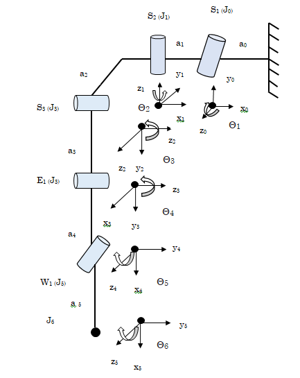
Figure 1: Graphical representation of Spatial 5R Exoskeleton
The specified twist angles are:
α1 = -90 °
α2 = -90 °
α4 = -90 °
Here,  refers to the link length,
 refers to the link offset,
 refers to the link twist and
 is the joint angle.
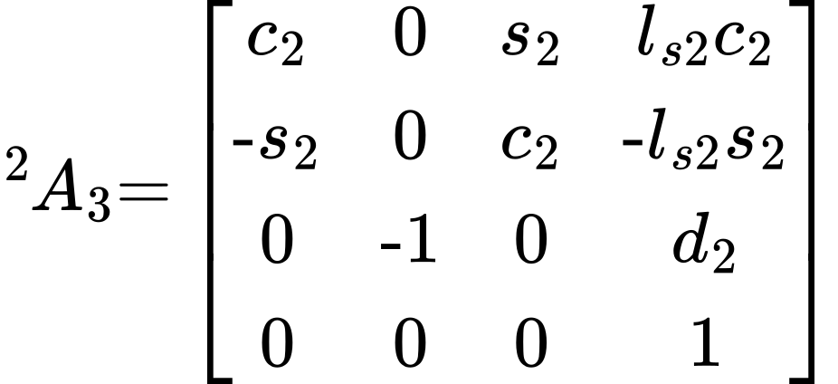
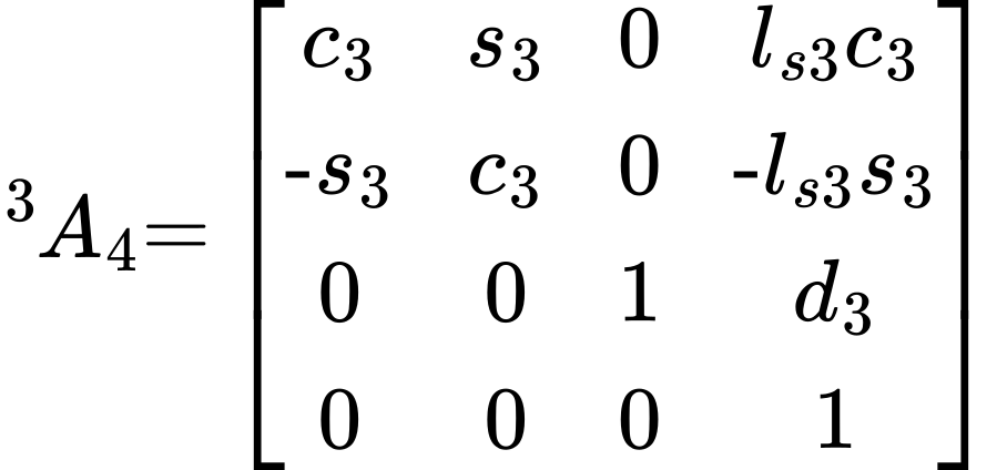
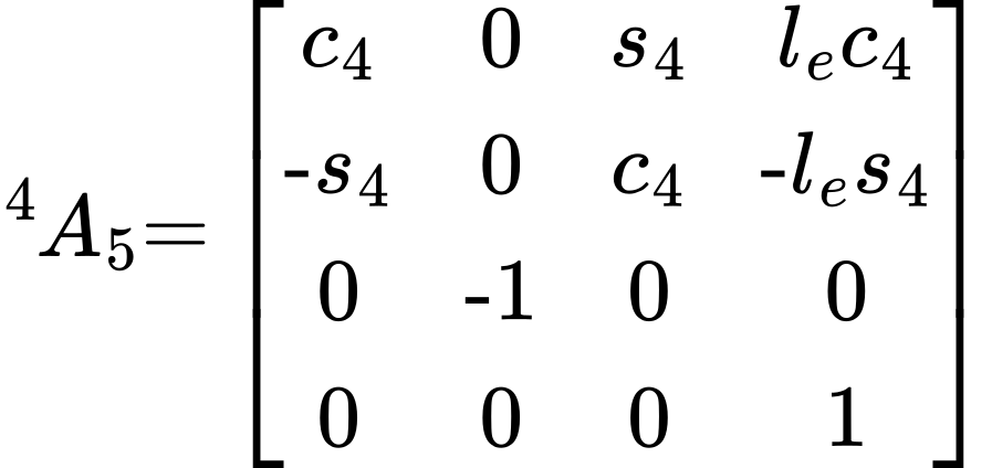
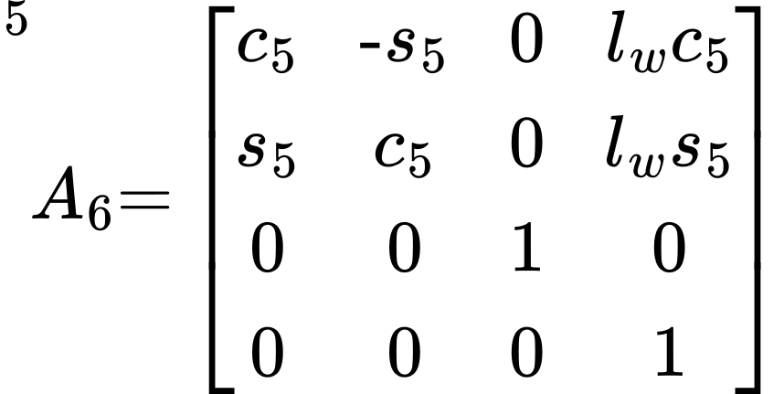
Denavit–Hartenberg Matrix for the Spatial 5R Exoskeleton
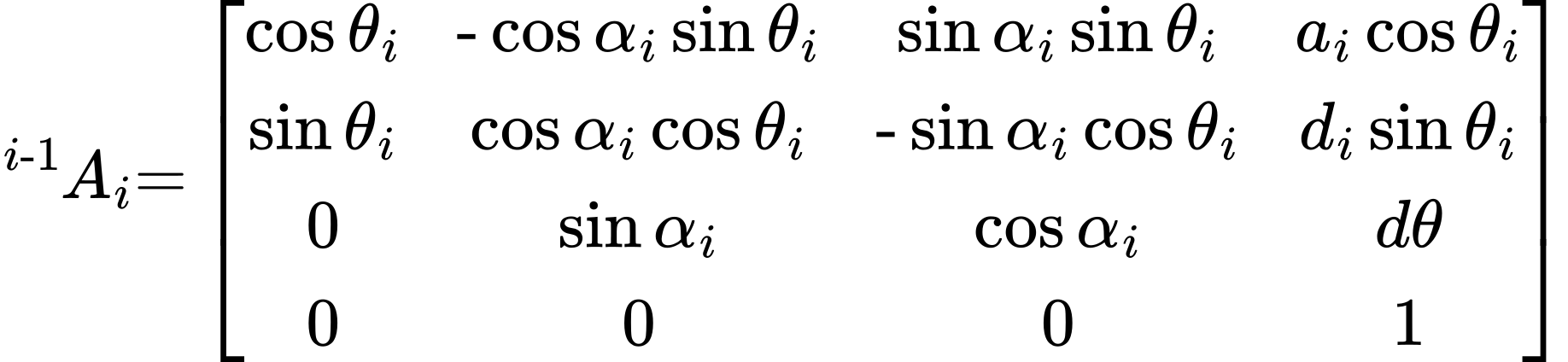 (1)
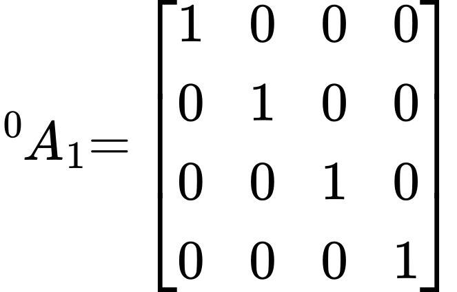 (2)
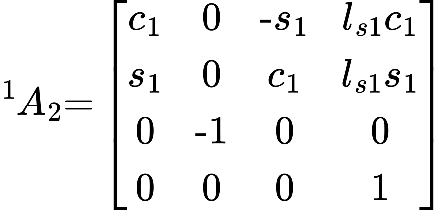 (3)
 (4)
 (5)
 (6)
 (7)
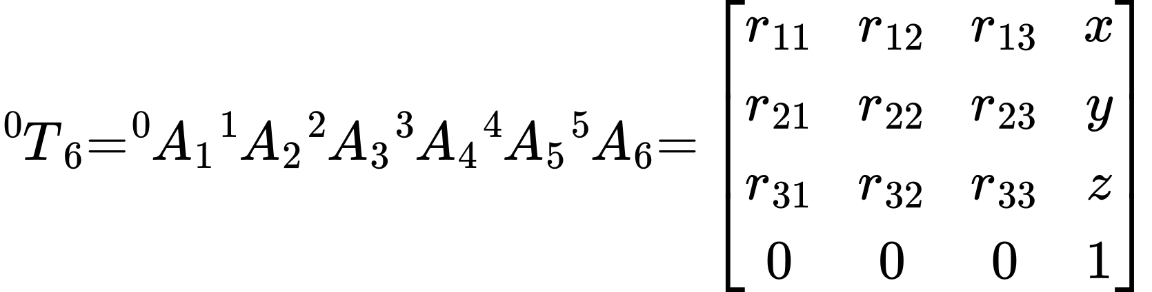 (8)
The end-effector spatial coordinates are represented as  and the total angle is given in Equation (9). The values of
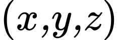 coordinates are defined in Equation (8).
 (9)
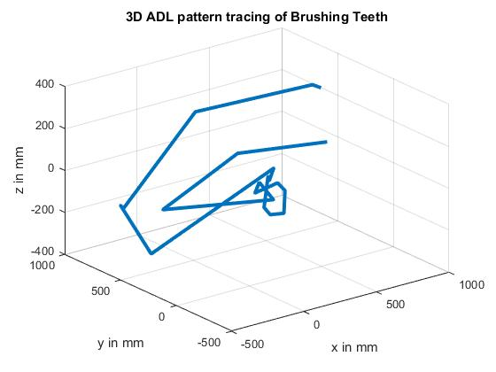
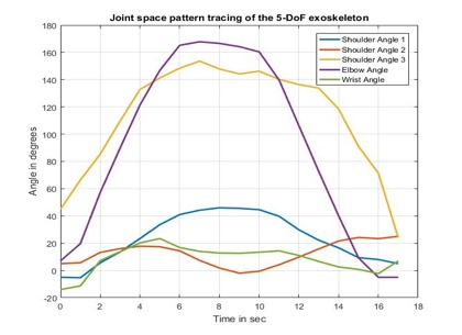
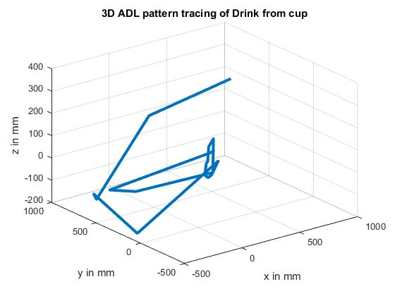
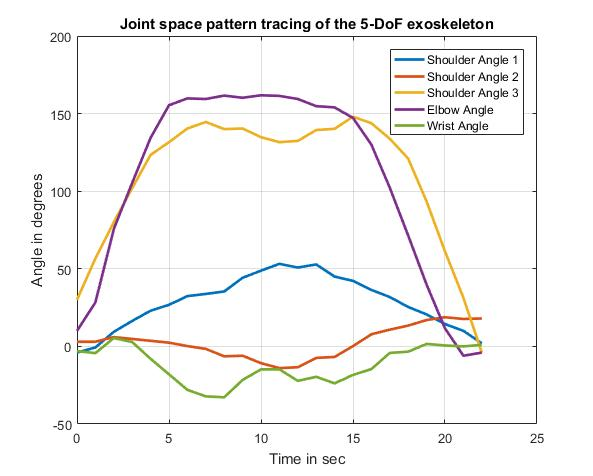
The end-effector positions in the workspace for respective shoulder 1, Shoulder 2, Shoulder 3, elbow and wrist angles are obtained using the 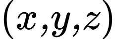 values from the matrix Equation (8). During the rehabilitation process, the sequence of coordinates of predefined exercise patterns involving shoulder – horizontal abduction/adduction, elbow – flexion/extension and wrist – flexion/extension movements are recorded with respect to the end-effector position of the Spatial 5R manipulating exoskeleton. Total angle of Exoskeleton is given in Equation (9). The recorded pattern is fed to the controller and when a deviation of any joint during the therapy is spotted, the error feedback is sent to the controller to adjust the movement as desired.
Selection of Activities of Daily Living
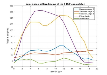
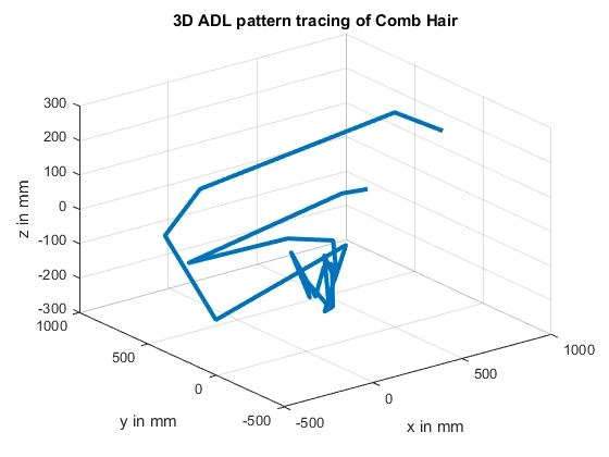
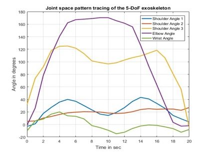
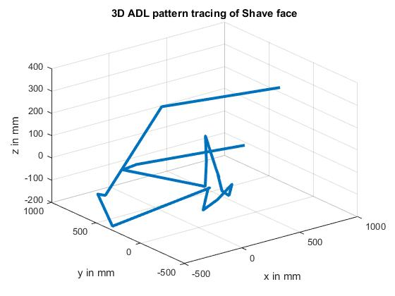
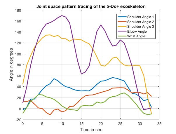
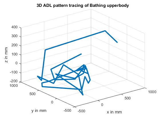
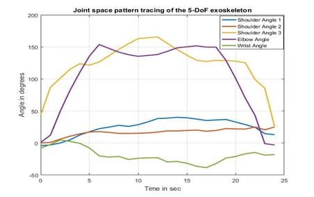
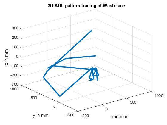
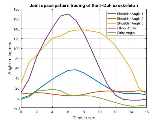
ADL tasks are selected according to their relevance to common activities performed at home [9]. The study groups the selected activities into grooming, feeding and bathing. Tasks include brushing teeth, drinking from a cup, combing hair, shaving, bathing the upper body, washing the face, using a spoon or fork, and cutting food. Table 2 lists the frequency scores, which range from six to eight. Dressing, toileting, mobility and social activities are excluded because they do not fit the study’s selected upper-limb task scope. Dressing also involves coordinated use of both hands, which is outside the proposed approach. Lower-body and hip movements are not considered.
ADL Training with an Exoskeleton and Virtual Reality
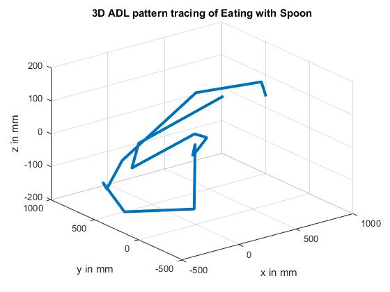
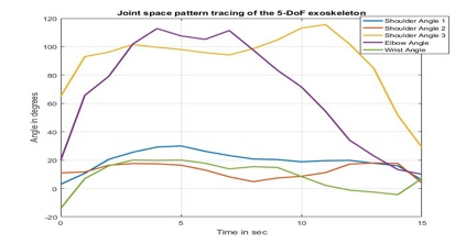
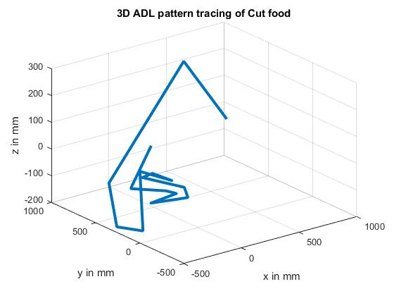
A five-degree-of-freedom test rig is constructed with measurements corresponding to the proposed exoskeleton. Potentiometers mounted at the joints connect to an Arduino Nano, and angle data are transferred through the serial monitor and saved for simulation. Measurements from healthy-adult ADL movements provide reference trajectories. The forward kinematic model is implemented in MATLAB to calculate end-effector positions and represent the joint space and workspace. Unity 3D provides a virtual environment that demonstrates the selected ADL tasks. During interaction with the rig, the sensors record movement angles for comparison with the reference patterns. Table 2 presents the resulting joint-space and workspace illustrations for the task demonstrations.
Table 2: ADL Activities Pattern Tracing
Domain | Task | Frequency Score | Joint space | Work Space |
Grooming | Brush Teeth | 8 |
|
|
Feeding | Drink from cup | 8 |
|
|
Grooming | Comb Hair | 7 |
|
|
Grooming | Shave Face | 7 |
|
|
Bathing | Bathing Upper Body | 6 |
|
|
Grooming | Wash Face | 6 |
|
|
Feeding | Use Spoon/Fork | 6 |
|
|
Feeding | Cut food | 6 |
|
|
Conclusion
The proposed platform integrates a five-degree-of-freedom upper-limb mechanism, joint-angle sensing and a virtual environment for selected daily activities. Forward kinematic modelling connects the recorded angles to spatial end-effector positions. Healthy-adult movement patterns provide reference trajectories for comparison, while the virtual tasks offer an interactive presentation of the movements. The design is intended to support portable rehabilitation research and instructor review of recorded performance. The reported kinematic analysis and task illustrations describe the engineering integration; individual clinical use would depend on professional assessment and appropriate evaluation.
Acknowledgment
The authors would like to thank the Electrical and Electronics Engineering Department of PSG College of technology, Coimbatore for the support. This research was financially funded by the Department of Science and Technology of India under the Biomedical Device and Technology (BDTD) Scheme.
References
1. Gueye T, Dedkova M, Rogalewicz V, et al (2021) Early post-stroke rehabilitation for upper limb motor function using virtual reality and exoskeleton: equally efficient in older patients. Neurol Neurochir Pol 55:91–96. https://doi.org/10.5603/PJNNS.A2020.0096
2. Hong M, Kim S, Um T, et al KULEX: An ADL power-assistance demonstration. ieeexplore.ieee.org
3. Gharaei A, Amiri M, Karami R, et al Mechanical design, simulation and nonlinear control of a new exoskeleton robot for use in upper-limb rehabilitation after stroke. ieeexplore.ieee.org. https://doi.org/10.1109/ICBME.2013.6782183
4. Naidu D, Stopforth R, Bright G, et al A 7 DOF exoskeleton arm: Shoulder, elbow, wrist and hand mechanism for assistance to upper limb disabled individuals. ieeexplore.ieee.org
5. Soltani-Zarrin R, Zeiaee A, et al, A computational approach for human-like motion generation in upper limb exoskeletons supporting scapulohumeral rhythms. ieeexplore.ieee.org
6. Fernández-Vázquez D et al, (2022) Haptic Glove Systems in Combination with Semi-Immersive Virtual Reality for Upper Extremity Motor Rehabilitation after Stroke: A Systematic Review and Meta. mdpi.com 19:10378. https://doi.org/10.3390/ijerph191610378
7. Li N, Yu P, Yang T, et al (2017) Bio-inspired wearable soft upper-limb exoskeleton robot for stroke survivors. ieeexplore.ieee.org. https://doi.org/10.1109/ROBIO.2017.8324826
8. Hong M, Kim S, 9th international conference, 2012, Development of a 10-DOF robotic system for upper-limb power assistance. ieeexplore.ieee.org
9. He C, Xiong C, Chen Z, et al Preliminary Assessment of a Postural Synergy-Based Exoskeleton for Post-Stroke Upper Limb Rehabilitation. ieeexplore.ieee.org
National Institute of Neurological Disorders and Stroke. (n.d.). Stroke Recovery. https://www.ninds.nih.gov/health-information/stroke/recovery
Cite This Work
To export a reference to this article please select a referencing stye below:

Academic Master Education Team is a group of academic editors and subject specialists responsible for producing structured, research-backed essays across multiple disciplines. Each article is developed following Academic Master’s Editorial Policy and supported by credible academic references. The team ensures clarity, citation accuracy, and adherence to ethical academic writing standards
Content reviewed under Academic Master Editorial Policy.