
 Electrical Engineering
Textbook
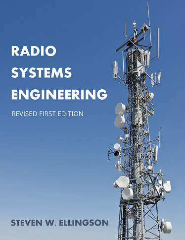
Radio Systems Engineering
Not rated yetRate this bookSteven W. Ellingson’s radio engineering text connects physical principles, link analysis, and hardware design. Its systems framework helps readers relate a component’s behaviour to the performance of an entire communication link.
Free reading is available at the official source. Opens in a new tab.
 Free
About this book
Radio Systems Engineering develops a systems view of radio by connecting antennas, propagation, noise, modulation, circuits, and digital implementation. The eighteen chapters show how component choices affect a complete communication link rather than treating radio as a collection of independent formulas. The guide follows those chapters and the two technical appendices. It emphasizes the distinction between signal strength, signal quality, bandwidth, linearity, and efficiency. Examples of particular systems, frequency allocations, and technologies belong to the source edition; current operational or regulatory requirements require separate authoritative checks.
The detailed guide below follows the book’s chapter, unit, or section structure. Read it alongside the study instructions and the complete official text.
Book summary
Chapter-by-chapter summaries
Chapter 1: Introduction
A radio link converts information into a transmitted signal, carries it through an electromagnetic channel, and recovers it at a receiver. The opening chapter introduces the frequency spectrum, link architecture, integration levels, and specifications. Different applications impose different priorities for range, bandwidth, power, cost, and reliability. A component cannot be judged only by its best isolated specification because the complete link must meet several constraints at once. The chapter supplies the system map used throughout the book and establishes why communication performance depends on the relationships among blocks.
Chapter 2: Antenna Fundamentals
Antennas connect guided electrical signals with propagating electromagnetic fields. The chapter develops radiation, reception, patterns, reciprocity, polarization, and common antenna forms. Directivity describes how radiation is distributed, while gain also reflects efficiency under the relevant definition. Polarization and orientation affect coupling between antennas even when transmitted power is unchanged. Dipoles, monopoles, patches, arrays, and high-gain structures provide different tradeoffs. The key lesson is that an antenna is part of a physical environment and interface, not simply a device with one gain number.
Chapter 3: Propagation
Propagation determines how a signal changes between transmitter and receiver. Free-space loss is a useful reference, but reflection, transmission, terrain, multipath, and atmospheric effects create more complex channels. The chapter distinguishes fading and frequency-dependent behavior and considers different frequency regimes. A direct path can coexist with reflected paths that reinforce or cancel at particular locations. Average received power does not describe every short-term or narrowband impairment. Link design therefore needs a channel model appropriate to the setting rather than universal application of a free-space formula.
Chapter 4: Noise
Noise limits the ability to recover information from a signal. The chapter develops thermal and nonthermal sources, equivalent noise descriptions, noise figure, and cascaded devices. Bandwidth matters because integrating noise across a wider range generally changes the total noise power. Gain early in a chain can reduce the relative importance of later added noise, but other constraints still apply. External noise and antenna coupling also contribute. The distinction between a device's noise property and the total receiver-system performance becomes important when selecting and ordering components.
Chapter 5: Analog Modulation
Analog modulation places information in variations of a carrier's amplitude, frequency, or phase. The chapter uses complex-baseband representation to connect apparently different waveforms and introduces AM, single-sideband, and FM. Each approach uses bandwidth and power differently and responds differently to noise. A representation is useful because it separates the carrier from the information-bearing variation without implying that the underlying signal is physically complex-valued. The chapter connects spectrum, demodulation, and performance, preparing the reader to compare modulation methods through the requirements of a link.
Chapter 6: Digital Modulation
Digital communication maps information into symbols and waveforms, with choices affecting bandwidth, energy efficiency, error performance, and synchronization. The chapter develops modulation formats, pulse shaping, detection, coding, fading, intersymbol interference, and multicarrier or spread-spectrum ideas. Higher spectral efficiency can require better signal quality, so more bits per symbol are not a free improvement. Bit-energy and noise-density measures help compare systems under stated assumptions. Timing, carrier phase, and frequency recovery remain essential: an ideal constellation does not by itself guarantee a working receiver.
Chapter 7: Radio Link Analysis
Link analysis combines transmit power, losses, antenna properties, propagation, receiver noise, and required performance into a coherent budget. Decibel notation simplifies multiplication into addition when quantities and reference units are handled correctly. Power in dBm is not the same kind of quantity as a dimensionless loss in dB. The chapter's examples show how a margin can accommodate uncertainty and variation, but a budget is only as credible as its assumptions. The useful result is an explanation of what limits the link and which change would improve it.
Chapter 8: Two-Port Concepts
A two-port model describes how a component interacts with signals at its input and output. Scattering parameters are especially useful at radio frequencies, where wave relationships and impedance matter. The chapter connects reflection, transmission, gain, and the behavior of active devices. Specified reference impedances and operating conditions are part of the meaning of a parameter. A linear model can describe small-signal behavior while failing at larger amplitudes. Understanding that boundary prevents using a convenient network representation beyond the conditions in which it is valid.
Chapter 9: Impedance Matching
Matching networks manage the relationship between source and load impedances. The chapter compares approaches and shows why an unmatched interface can reduce delivered power or alter system behavior. Reactive and resistive strategies have different losses, bandwidths, and implementation constraints. A match at one frequency may not remain effective across a broad band. The desired match can also depend on whether the design prioritizes power transfer, noise, stability, or another criterion. The chapter develops matching as a purposeful design choice rather than a rule to make every interface identical.
Chapter 10: Amplifiers
Amplifier design connects device behavior with gain, noise, matching, stability, and power constraints. The chapter develops transistor-based models and network methods for evaluating operating conditions. A high-gain solution is not automatically acceptable if it is unstable or poorly suited to the required noise or output performance. Input and output choices interact, and the practical device has limits absent from an ideal gain block. The chapter encourages interpreting calculations as part of a constrained design problem, with the selected model and signal level stated explicitly.
Chapter 11: Linearity, Multistage Analysis, and Dynamic Range
Real devices depart from proportional response and generate distortion, compression, and intermodulation. The chapter explains how those effects accumulate through cascaded stages and constrain usable signal levels. Dynamic range depends on both weak-signal limitations and strong-signal behavior, so improving noise alone does not solve every problem. Intercept-point concepts provide useful approximations within their assumptions. A receiver can be affected by strong unwanted signals even when the desired signal is small. System analysis therefore needs the levels and ordering of stages, not merely their individual headline specifications.
Chapter 12: Antenna Integration
Integrating an antenna with a radio introduces mismatch, losses, noise, and interface effects that idealized link diagrams can hide. The chapter combines antenna and circuit descriptions to evaluate how available power becomes useful received or transmitted power. Feed networks and connections can change the practical benefit of an antenna's nominal characteristics. The analysis also clarifies how antenna temperature and losses contribute to a receiver. The chapter's central lesson is to keep the reference plane and physical interface explicit when moving between an antenna specification and a complete system budget.
Chapter 13: Analog Filters and Multiplexers
Filters shape which frequencies pass through a system and with what attenuation and phase behavior. The chapter introduces response characteristics and common approximation families, alongside practical implementations and multiplexing. Passband, stopband, transition width, insertion loss, and ripple describe different aspects of performance. A sharper response may involve other costs or constraints. Filters can protect later stages from unwanted energy, but their losses and placement affect noise and dynamic range. Selection therefore follows the whole receiver or transmitter requirement rather than a preference for the narrowest possible response.
Chapter 14: Frequency and Quadrature Conversion in the Analog Domain
Frequency conversion moves a signal to a more convenient part of the spectrum while preserving the information needed for recovery. Mixing produces multiple components, making filtering and image considerations important. Quadrature representations separate signal components in a way useful for modulation and demodulation. The chapter connects the mathematical operation with practical mixers and their nonideal behavior. Conversion is not simply relabeling a frequency: loss, noise, leakage, and unwanted products can affect the system. The design must account for those effects at the relevant signal levels.
Chapter 15: Receivers
Receiver architecture determines how selection, amplification, conversion, and digitization work together. The chapter compares arrangements and examines practical issues such as analog-to-digital conversion and preselection. A receiver must recover a weak desired signal while tolerating other signals and its own internal limitations. Moving more work into the digital domain changes where constraints occur rather than eliminating them. Sampling and quantization need to fit the preceding analog design. The chapter brings earlier topics together into a system whose success depends on coordinated choices across several stages.
Chapter 16: Frequency Synthesis
Radio systems need stable and controllable frequency sources. The chapter develops oscillator and synthesis concepts and examines phase noise and spurious responses. A nominally correct carrier frequency is not the whole specification: fluctuations and unwanted components can affect modulation quality and reception of nearby signals. Frequency control, tuning, and stability create tradeoffs that depend on the application. The chapter connects source behavior with effects elsewhere in the link, demonstrating why an oscillator cannot be evaluated solely by its center frequency or tuning range.
Chapter 17: Transmitters
Transmitters combine modulation, frequency conversion, amplification, and filtering to deliver an information-bearing signal. The chapter examines architectures and power-amplifier behavior, including efficiency and linearity tradeoffs. A waveform with varying amplitude may impose different demands from a constant-envelope signal. Increasing output power can create distortion or unwanted emissions if the chain is not designed for it. The system must also manage losses and heat. The chapter asks readers to relate the selected architecture to the intended waveform and operating constraints rather than maximize one component's output in isolation.
Chapter 18: Digital Implementation of Radio Functions
Digital processing can implement filtering, conversion, and other functions using sampled signals. The chapter introduces digital filter concepts and the relationships among sample rate, bandwidth, and realizable response. Finite processing and representation create constraints that ideal mathematical filters do not have. Digital implementation remains connected to analog interfaces: aliasing, sampling, and converter behavior affect what the processing can recover. The concluding chapter shows how the same radio functions can be distributed across analog and digital stages, with architecture chosen to balance performance, flexibility, and practical cost.
Appendices: Empirical Path-Loss Models and Common Systems
The appendices provide reference context for average path-loss estimation and characteristics of selected radio systems. Empirical models summarize observations within particular environments and frequency or distance ranges; their coefficients are not universal physical constants. Likewise, system examples illustrate combinations of requirements and design choices from the source edition. Use them to understand relationships and assumptions, then check current official specifications before applying a historical example operationally.
Study instructions
Begin with a block diagram of a radio link and annotate where information changes representation. As each component is introduced, record both its local function and the system requirement it helps satisfy. Keep a separate list of prerequisite concepts that need revision rather than trying to infer them from a complicated example.
When studying Radio Link Analysis, trace each quantity back to a physical assumption. Distinguish a theoretical model, a specification, and a measured result. Work from the original derivations and course exercises; this guide does not validate a hardware design or establish operating authorization.
Full-book practice and review: Build a link-analysis notebook that carries assumptions from antennas, propagation, noise, and modulation into the later receiver and transmitter chapters. Keep linear quantities distinct from logarithmic units and state reference levels. When comparing a component or architecture, connect gain, bandwidth, matching, linearity, and dynamic range with system performance. Check a numerical result against a limiting case and explain which implementation constraint could prevent an apparently adequate link budget from working as intended.
Questions for reflection
- How can a system requirement constrain a component choice?
- Why is propagation part of the engineering problem?
- Which communication questions fall outside the book’s stated scope?
The study suggestions and questions are independent Academic Master editorial material.
Sources and coverage
These original summaries draw on the source text, including chapter or section introductions and selected explanations, examples, exercises, and review material. They are condensed study guides, not a page-by-page account or a replacement for the complete resource. Additional synthesis sections are identified separately.
About access & copyright
This page provides book information and study material. Full-text access is provided by the original publisher or authorised source; a listing does not grant permission to republish the book.
Read our Library Access & Copyright policySystems thinking
Relate component behaviour to link performance.
Physical representation
Connect frequency, wavelength, and environment.
Prerequisites
Identify the engineering knowledge assumed.
Model limits
Keep assumptions and measured results distinct.
Reader ratings & reviews
Share your thoughts
Your review helps other students choose the right resources.
KEEP LEARNING
Your next great read
Electrical Engineering Engineering & Technology
Aerospace Structures
View Aerospace Structures — book Civil Engineering
Traffic Flow Theory: An introduction with exercises
View Traffic Flow Theory: An introduction with exercises — book Civil Engineering
Ports and Waterways: Navigating the changing world
View Ports and Waterways: Navigating the changing world — book Engineering & Technology
Building with Nature & Beyond: Principles for designing nature based engineering solutions
View Building with Nature & Beyond: Principles for designing nature based engineering solutions — book Applied
Introduction to Probability
View Introduction to Probability — book Civil Engineering
Basics of Fluid Mechanics
View Basics of Fluid Mechanics — book Business
Developing New Products and Services
View Developing New Products and Services — book Engineering & Technology
Notes on Diffy Qs: Differential Equations for Engineers
View Notes on Diffy Qs: Differential Equations for Engineers — book Electrical Engineering