
Principles of Mechanics
Engineering & TechnologyTextbook
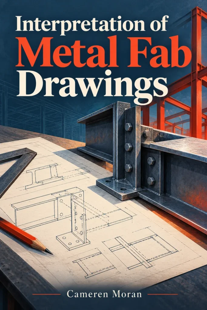
Interpretation of Metal Fab Drawings
Not rated yetRate this bookInterpretation of Metal Fab Drawings introduces fabrication drawings and welding symbols as a shared technical language. Cameren Moran connects blueprint interpretation with communication among welders, engineers and quality-control staff.
 Free
About this book
The introductory chapter describes a course that applies industrial fabrication drawings through classroom and shop assignments. It connects interpretation with planning, layout and practical fabrication, and identifies American Welding Society symbols as part of the learning scope. The verified contents review blueprints, joint terminology, symbol families, processes and pipe drawings. Diagrams are central to this material and should be consulted in the source. This guide explains the introductory purpose; it does not substitute for the relevant drawing, current standard or supervised technical instruction.
The attached edition contains 104 PDF pages, including front matter. Cover: source edition title page rendered from the PDF. The textbook and its original notices are retained; Academic Master’s study material is separate from the source text.
Book summary
Interpretation of Metal Fab Drawings develops drawing literacy for fabricated and welded components. The linked workbook progresses through blueprint review, joint terminology, welding symbols, weld families, process notation, and piping. This guide follows all twelve main teaching sections after the introduction. The original symbol diagrams are essential: a short verbal summary cannot substitute for reading the symbol, its placement, and its dimensions together.
Chapter-by-chapter summaries
Blueprint Review
The opening review reconnects views, lines, dimensions, and spatial reasoning with fabrication. Read a drawing as a coordinated description rather than a collection of independent marks. A feature visible in one view may need another view or a note to become unambiguous. Establish overall form and units before interpreting detailed instructions, and distinguish specified information from assumptions made to complete a mental picture.
Joint Types and Terminology
Joint terminology describes how components meet, while a weld describes material and geometry joining them. These are related but different classifications. Use the source illustrations to compare arrangements and name the relevant surfaces or edges. A correct label should remain meaningful when the assembly is rotated. This vocabulary provides the basis for later symbol interpretation and helps avoid mistaking a familiar joint for a fully specified weld.
Basics of Welding Symbols
A welding symbol combines reference structure, location, and additional information. Position matters, so the same mark cannot be interpreted independently of where it appears. Identify the arrow and reference line before reading dimensions or other instructions. Practice translating a complete symbol into a description and drawing that description back. A partial recognition of the central mark is not enough to determine the intended fabrication requirement.
Supplementary Welding Symbols
Supplementary marks add information about execution, extent, or finish. They should be read with the main weld symbol and notes rather than as isolated commands. The chapter’s examples show how a small addition changes the interpretation. Build comparison pairs that differ in one feature and explain the resulting change. Preserve the distinction between a contour requirement and a method or process instruction when the source treats them separately.
Fillet Weld Symbols
Fillet-weld notation communicates placement and relevant dimensions or extent. Trace which side or sides are indicated and relate the symbol to the joint’s actual geometry. A number’s role depends on its position in the notation. Compare a continuous and a segmented requirement using the original diagrams. The study aim is an unambiguous reading, not an assumption that every visually similar joint receives the same fillet weld.
Groove Welding Symbols
Groove symbols describe a family of preparations and weld requirements whose geometry must be understood spatially. Identify the preparation, relevant side, and associated dimensions before combining the information into one instruction. Do not infer that a groove’s drawing appearance alone establishes every requirement. Compare source examples by changing one parameter or symbol feature and explaining what the fabricator or inspector would need to understand differently.
Plug Weld Symbols
Plug-weld notation concerns joining through openings and includes information that must be related to the component arrangement. Distinguish the opening’s geometry from the completed weld and check what dimensions are actually specified. Use the section’s exercises to connect symbol placement with the intended joint. A complete reading should identify the relevant components and extent without inventing a manufacturing detail absent from the print.
Spot, Seam, and Stud Welding Symbols
These families use different joining arrangements and should not be collapsed into one interpretation because their symbols appear compact. Compare what each identifies, how its placement is shown, and which measurements or counts matter in the examples. Follow the source conventions to interpret the entire requirement. The chapter broadens symbol literacy by showing how a common notation framework communicates several physically different operations.
Edge Weld Symbols
Edge-weld examples connect component edges with a particular joining requirement. Examine the arrangement before assigning meaning to the symbol, then identify relevant dimensions and extent. A projected view can conceal which pieces meet, so cross-check other views. Explain what the drawing requires while keeping the method of achieving it separate unless that method is explicitly specified. The original examples are necessary for recognizing the geometric distinctions.
Process and Method
Process and method information adds another level to the drawing’s instructions. Read abbreviations and notes within the system used by the source and distinguish a required process from an inferred shop preference. A symbol describing the finished joint does not automatically specify every operational detail. Record unfamiliar notation for verification rather than expand it from memory when the consequence would affect interpretation.
Pipe Symbols
Piping symbols represent components and functions through a specialized vocabulary. A schematic symbol is not necessarily a picture of the component’s physical shape. Identify the kind of drawing and the information its symbols are meant to communicate. Compare similar marks carefully and maintain a checked legend. This prepares the transition from individual weld or joint details to the organization of a larger connected system.
Pipe Drawings
Pipe drawings combine component identification, routing, relationships, and dimensions. Trace the system in a consistent direction and use the relevant views to understand changes in orientation. Distinguish schematic connectivity from physical layout and fabrication dimensions. The final section integrates the workbook’s central skill: relating notation to a coherent object or assembly. Document unresolved ambiguities instead of silently filling them with a familiar but unsupported arrangement.
Study instructions
- Use the original diagrams and keep a checked symbol glossary beside each exercise.
- Identify the drawing type, units, reference structure, and relevant view before interpreting details.
- Translate symbols into words and a simple sketch, then compare the three representations.
- Practice pairs that differ in one mark or dimension and explain its effect.
- Separate stated fabrication requirements from process assumptions and shop preferences.
- Complete a full-print interpretation listing both requirements and any questions needing clarification.
Questions for reflection
- Which information comes from a symbol’s location rather than its shape?
- How do joint type and weld type answer different questions?
- When does a schematic connection fail to specify the physical layout?
Sources and coverage
This original study guide follows the complete linked source edition and all of its substantive chapters or named teaching sections. It condenses their main ideas and relationships; the study tasks are guidance for reading alongside the complete resource. It does not reproduce the source exercises or answer key. Book source; Complete source PDF.
About access & copyright
Check this edition’s source and licence before reusing its files or content. A library listing does not grant additional rights.
Read our Library Access & Copyright policyShared language
Relate drawings to technical communication.
Applied interpretation
Connect classroom reading with practical tasks.
Symbol scope
Identify the verified families of topics.
Visual context
Consult diagrams and their stated standard.
Reader ratings & reviews
Share your thoughts
Your review helps other students choose the right resources.
KEEP LEARNING
Your next great read
Classical mechanics
Understanding Acoustics
Understanding Acoustics
View Understanding Acoustics — book Engineering & Technology
Aerospace Structures
View Aerospace Structures — book Dynamics
Introductory Dynamics: 2D Kinematics and Kinetics of Point Masses and Rigid Bodies, Edition 1.1
View Introductory Dynamics: 2D Kinematics and Kinetics of Point Masses and Rigid Bodies, Edition 1.1 — book Civil Engineering
Traffic Flow Theory: An introduction with exercises
View Traffic Flow Theory: An introduction with exercises — book Civil Engineering
Ports and Waterways: Navigating the changing world
View Ports and Waterways: Navigating the changing world — book Engineering & Technology
Building with Nature & Beyond: Principles for designing nature based engineering solutions
View Building with Nature & Beyond: Principles for designing nature based engineering solutions — book Applied
Introduction to Probability
View Introduction to Probability — book Civil Engineering
Basics of Fluid Mechanics
View Basics of Fluid Mechanics — book Business