
Principles of Mechanics
Engineering & TechnologyTextbook
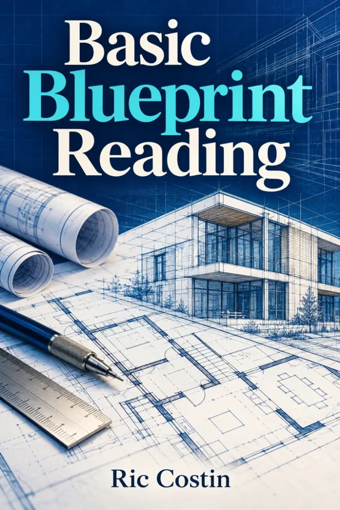
Basic Blueprint Reading
Not rated yetRate this bookBasic Blueprint Reading introduces the graphic language used to communicate a design. Ric Costin’s Linn-Benton Community College resource covers lines, visualisation, sketching, scale, dimensions, views and print interpretation for technical and trade students.
 Free
About this book
The introduction describes blueprint reading as a practical skill for producing accurate parts and fabrications. Drawings communicate what is to be made, the required materials and the relevant specifications. The book updates an earlier Linn-Benton engineering and drafting publication for the welding department. Its verified chapters begin with the language of lines and move through visualisation, sketching, scaling and dimensions before considering specialised views and features. The source’s diagrams are important to the learning activities and should be consulted directly alongside the written explanations.
The attached edition contains 137 PDF pages, including front matter. Cover: source edition title page rendered from the PDF. The textbook and its original notices are retained; Academic Master’s study material is separate from the source text.
Book summary
Ric Costin’s Basic Blueprint Reading develops the ability to turn a technical drawing into an accurate understanding of an object and its manufacturing requirements. The Linn-Benton Community College resource progresses through line conventions, visualization, sketching, scale, dimensions, auxiliary and sectional views, machined features, and complete print interpretation. Read the original drawings alongside this guide: their spatial information cannot be replaced by a verbal description alone.
Chapter-by-chapter summaries
The Language of Lines
Line conventions distinguish visible edges, hidden features, centers, dimensions, and other information within the same drawing. A line’s meaning depends on its pattern and context rather than simply where it appears on the page. Start by identifying the object outline, then examine what other line types add to that account. Distinguish a physical edge from a construction or reference mark. Reading these conventions consistently prevents a common beginner’s mistake: treating every mark as a feature that should exist on the finished part. Practice explaining a small drawing using the line vocabulary before attempting to reconstruct the entire object.
Visualization
Multiple views supply complementary information about a three-dimensional object. Features that are clear in one projection can be hidden or ambiguous in another, so visualization involves checking views against each other. Align corresponding locations and ask how a surface or opening would appear from another direction. A convincing interpretation must fit all the supplied views, not merely resemble one of them. Sketch a tentative solid, identify any uncertainty, and use the remaining information to test it. This develops a disciplined spatial process rather than dependence on a sudden visual impression that may conceal a missing or impossible feature.
Technical Sketching
Sketching communicates shape and relationships without requiring a fully finished instrument drawing. Proportion, orientation, and clear line use make a sketch intelligible to another person. The section connects visual thinking with communication: drawing a feature can reveal that its spatial relationship is not yet understood. Begin with the overall form, add major divisions, and then indicate details. A sketch should preserve the relationships needed for its purpose even when it is not drawn at an exact scale. Compare your sketch with the source views and revise inconsistencies before treating it as a reliable representation.
Scaling
Scale expresses the relationship between a drawing’s displayed size and the actual object. Enlarged and reduced representations allow details or large objects to fit a usable sheet, but physical measurement on a displayed or printed copy can be misleading. Read the stated scale and supplied dimensions rather than infer actual size from appearance. Practice converting between drawing and object measurements while keeping units explicit. A copied image may have been resized, so dimensioned information has a different authority from a ruler measurement on that copy. The central skill is recognizing the representation’s relationship to the object without confusing the two.
Dimensioning
Dimensions specify size and location in a form intended to support construction and inspection. Understand what each number refers to, where its extension lines begin, and how it relates to other specified features. Locate the controlling reference before combining measurements. Distinguish an overall dimension from a chain of smaller ones and identify which values are explicitly given rather than calculated. The goal is to extract a coherent set of requirements, not collect numbers independently. A useful check is to describe how the dimension would be verified on the finished part and whether your interpretation leaves an important feature undefined.
Auxiliary Views
An inclined surface may appear shortened or distorted in the principal views. An auxiliary view introduces a direction that reveals information those projections cannot display directly. Follow how locations are transferred and why the selected viewing direction is useful. Distinguish the true shape of the surface from its projected appearance. When reconstructing an example, identify the particular uncertainty the auxiliary view resolves. This helps the learner see an additional view as a deliberate solution to a communication problem rather than another picture that must be memorized without understanding its relationship to the original views.
Sectional Views
A section imagines a cut through an object so that interior features become easier to communicate. The cutting-plane indication, viewing direction, and section conventions work together to specify what the reader sees. Identify which surfaces are exposed by the imagined cut and which features remain beyond it. Section lining is a drawing convention, not a pattern that must be manufactured on the surface. Compare the section with the external views to reconstruct the complete object. The section should simplify internal geometry without encouraging the reader to mistake the cut representation for the object’s actual external shape.
Machined Features
The workbook introduces features encountered in manufacturing and the drawing information used to describe them. A reader must connect a feature’s shape with its location and specified requirements. Holes, recesses, and other details may need more than one view or a note to become unambiguous. Examine each source example and explain what material is present or removed. Keep the physical feature separate from the symbols used to represent it. When a detail is unfamiliar, work from the supplied conventions and full print rather than assume that its appearance in one view establishes its complete geometry.
Print Interpretation
The final section integrates conventions, spatial reasoning, dimensions, and details into reading a complete print. Begin with the drawing’s general identification and overall form, then inspect views, notes, dimensions, and specific features systematically. Cross-check information rather than read each area in isolation. Record unresolved questions before making an assumption that could affect fabrication. A successful interpretation allows another person to understand the same object and requirements from your explanation. Use the workbook exercises to test that process, referring back to the relevant section whenever an error comes from a convention rather than a calculation.
Study instructions
- Keep the source drawings open and identify the function of each line type before interpreting a part.
- Sketch an object from its views, then explain how every important feature appears in at least two views.
- Record units, stated dimensions, and scale separately; do not infer a required size from a resized image.
- For auxiliary and section views, state the problem the additional view solves.
- Complete a full-print checklist covering shape, dimensions, internal features, notes, and uncertainties before checking your answers.
Questions for reflection
- What additional information does a hidden line provide that an outline does not?
- When would a principal view fail to reveal a surface’s true shape?
- Which parts of your interpretation are explicitly specified and which are assumptions?
Sources and coverage
This original study guide follows the complete linked source edition and all of its substantive chapters or named teaching sections. It condenses their main ideas and relationships; the study tasks are guidance for reading alongside the complete resource. It does not reproduce the source exercises or answer key. Book source; Complete source PDF.
About access & copyright
Check this edition’s source and licence before reusing its files or content. A library listing does not grant additional rights.
Read our Library Access & Copyright policyGraphic communication
Relate drawings to materials and specifications.
Line conventions
Recognise different purposes of visible and hidden lines.
Reading sequence
Identify the route into views and print interpretation.
Visual study
Consult diagrams rather than relying on prose alone.
Reader ratings & reviews
Share your thoughts
Your review helps other students choose the right resources.
KEEP LEARNING
Your next great read
Classical mechanics
Understanding Acoustics
Understanding Acoustics
View Understanding Acoustics — book Engineering & Technology
Aerospace Structures
View Aerospace Structures — book Dynamics
Introductory Dynamics: 2D Kinematics and Kinetics of Point Masses and Rigid Bodies, Edition 1.1
View Introductory Dynamics: 2D Kinematics and Kinetics of Point Masses and Rigid Bodies, Edition 1.1 — book Civil Engineering
Traffic Flow Theory: An introduction with exercises
View Traffic Flow Theory: An introduction with exercises — book Civil Engineering
Ports and Waterways: Navigating the changing world
View Ports and Waterways: Navigating the changing world — book Engineering & Technology
Building with Nature & Beyond: Principles for designing nature based engineering solutions
View Building with Nature & Beyond: Principles for designing nature based engineering solutions — book Applied
Introduction to Probability
View Introduction to Probability — book Civil Engineering
Basics of Fluid Mechanics
View Basics of Fluid Mechanics — book Business