
DECAGON SHAPED MULTILAYER MICRO STRIP PATCH ANTENNA FOR BANDWIDTH IMPROVEMENT IN BROADBAND APPLICATIONS
*1Anil K. Rathod, 2Md Bakhar
1*Research Center, Department of ECE, Guru Nanak Dev Engineering College, Bidar, India
2Professor, Guru Nanak Dev Engineering College, Bidar, Indias
Abstract
The design and analysis of a multilayer decagon-shaped microstrip patch antenna for increased bandwidth in broadband applications are presented in this study. The ground plane of the proposed antenna has measurements of 144 x 84 mm and a thickness of 1.6 mm. The antenna is simulated using the High-Frequency Structure Simulator (HFSS), and various performance metrics including bandwidth, gain, directivity, return loss, Voltage Standing Wave Ratio (VSWR), and radiation pattern are evaluated. The primary goal of this study is to increase antenna bandwidth in order to meet the growing needs of contemporary broadband applications. The decagon shape is chosen to enhance the antenna's overall performance and optimise the radiation characteristics. The proposed antenna delivers increased bandwidth and increased efficiency by utilising multiple layers. The results of the simulation conducted through HFSS demonstrate the effectiveness of the designed model in achieving the desired performance parameters. To validate the simulation results, an experimental analysis was performed using a Vector Network Analyzer (VNA). The simulated and measured results are in good agreement, demonstrating the proposed design's accuracy and dependability. The radiation pattern is evaluated employing the anechoic chambers experimental method. The multilayer patch antenna in the shape of a decagon has a noticeable increase in bandwidth, making it a suitable choice for a variety of broadband applications. The antenna's performance in terms of gain, directivity, and radiation pattern indicates its appropriateness for use with contemporary communication systems. Additionally, the measurements of return loss and VSWR show good impedance matching and little signal reflection. The results made possible future improvements and breakthroughs in multilayer antenna technology to meet the rising needs of contemporary communication systems.
Keywords: Multilayer microstrip patch antenna, Decagon shape, HFSS, VNA, Bandwidth, and Anechoic chambers.
Introduction
Antennas have seen an increase in demand due to the wireless technology's quick development and growth. The antenna is one of the essential components for incorporated low-profile wireless communication, hence antenna miniaturisation is necessary to get the optimal design.[1]. To enable Wireless Local Area Network (LAN) and other next-generation wireless technologies, it is necessary to have the capacity for concurrent operation of wireless antennas in certain wireless applications. [2]. Due to important characteristics including, light weight, low profile, simplicity of incorporation with planar circuits, and affordable manufacture, microstrip patch antennas have seen increased use in recent years [3]. These benefits are especially important when multiple patches are placed in an array arrangement to create antennas with high gain with suitably designed emission models. For the majority of contemporary remote sensing, communication and radar, microstrip array antennas are desirable [4].
Microstrip patch antennas, on the other hand, could exhibit a narrowband behaviour as a result of their resonant characteristics [5]. Based on the given substrate specifications and thickness, it has been observed that the impedance bandwidth of a microstrip patch typically attains only a fraction of few percent. This limitation poses a significant challenge in the context of wideband applications [6]. Modern microwave systems are therefore very interested in approaches and architectures that focus on bandwidth broadening. The antenna bandwidth is directly influenced by the substrate characteristics [7]. The ground plane and microstrip patch can be regarded as a capacitor, where the energy retained increases with the decrease in the substrate's dielectric constant and thickness [8]. The antenna bandwidth is decreased while the resonator's merit factor rises as a result. For optimal broadband performance, it is recommended to utilize a substrate with a low permittivity and substantial thickness [9].
The compact size and light weight of microstrip antennas make them more popular for use in wireless communication and space applications [10]. Microstrip antennas include drawbacks such a limited bandwidth, low gain, and ineffective efficiency. Multilayered rectangular microstrip antennas can be used to fix these issues [11]. This can be accomplished by carefully balancing the thickness of the substrate and superstrate above and under the patch. The multilayer microstrip patch is also helpful for protecting the patch during flight from the sun, rain, physical harm, and naturally occurring ice layers [12]. The size of the patch must be reduced in order to increase bandwidth. A multiple layer dielectric substrate has been employed to increase the bandwidth in order to solve this issue [13]. The multilayer structure has the same properties over the target frequency band in addition to providing an improved impedance bandwidth. The impedance bandwidth and wide operating frequency range are improved by methods such as multilayer microstrip antennas and substrates with lower dielectric constant [14]. Broadband applications are made possible by the design of multilayer stacked patch antennas. As the air gap length rises, the two resonant frequencies get closer to one another. Two resonating modes in the dielectric regions can be coupled through the air gap to produce the resonant behaviour [15]. The proposed decagon shaped multilayer design structure allows for the achievement of a good bandwidth and gain. Processing costs are also inexpensive. HFSS software can be used to analyse parameters such as Radiation Pattern, Returns Loss, Directivity, Gain, VSWR, and Bandwidth.
The main contributions of this work are,
To improve the overall functionality and optimise its radiation properties a novel decagon-shaped multilayer microstrip patch antenna is designed using HFSS.
To boost the antenna's bandwidth in order to satisfy the expanding requirements of modern broadband applications.
To completely assess the antenna's performance several performance parameters, such as bandwidth, gain, directivity, return loss, VSWR, and radiation pattern are employed.
To evaluate the radiation pattern, the experimental method is analysed using the anechoic chambers.
Literature Review
Jothilakshmi, P., et al [16] have suggested a unique 2 GHz mobile satellite service (MSS) application-specific small microstrip stacked patch antenna. An air gap separated the two stacked patches that made up the antenna to reduce coupling loss. To handover microwave energy from the feed-line to the radiating patch, the ground plane included a slot. A low-cost FR4 substrate with log slots shaped like a plus symbol served as the foundation for the multilayer aperture-coupled antenna design. The suggested antenna has a small profile. The results of simulations and experiments that were done to assess different performance characteristics, including return loss, gain, bandwidth, and radiation patterns, are provided.
Venkatesh, P., et al [17] have created the 2.45 GHz microstrip patch antenna for use in Wi-Fi applications. With the help of the computer simulation technology (CST) microwave studio, the suggested antenna was simulated. Although many different antenna designs were used at the time to support the systems that were already in place, Microstrip Patch Antennas were developed in this study to satisfy the demands of low profile and tolerable gain. There was discussion of the simulation findings based on the crucial antenna performance evaluation parameters of return loss, gain, radiation power, and directivity.
Bansode, P., [18] had created a 5.62 GHz Microstrip patch array antenna on a FR4 substrate with a 4.4 dielectric constant. The MicroSAR imaging radar, a low-cost imaging radar, was designed to work with the antenna. The antenna has an 8 X 2 patch array that produced a simulated gain of 17.5 dB with a 5% bandwidth. Two double-sided copper-clad FR4 substrates were employed in the antenna's multilayer configuration. The common copper layer served as the ground plane, which was generated when the two substrates were in close proximity to one another.
Srivastava, H. and Tiwari, U. [19] have included the creation, analysis, and modelling of rectilinear and circular microstrip patch antennas. The suggested patch antennas were constructed on Rogers RT/duroid 5880 material using Ansys HFSS software, and their resonating frequency was 9 GHz, which is in the X band range. The values of the rectangular MPA were found to be higher than those of the circular MPA. While the gain and bandwidth of the circular MPA were higher than those of the rectangular MPA. The suggested antennas were determined to be appropriate for satellite, wireless, and radar applications.
Ajay, V.G., et al [20] have suggested an innovative technique for creating a Defected Ground Structure (DGS) based on Double Looped Complementary Split Ring Resonator (DLCSRR) arrays that would boost the bandwidth of a truncated microstrip patch antenna (MPA). The suggested antenna worked well for RFID and WLAN/Wi-Fi applications. An initial development of a truncated MPA without DGS was undertaken, characterised by a resonance frequency of 2.86 GHz and a bandwidth measuring 95.6 MHz. The resonant frequency was shifted to 2.47 GHz and the bandwidth was increased to 202.5 MHz due to the researchers' integration of a novel DLCSRR arrangement on the ground plane.
Hemanth, D.J., et al [21] have presented a small, highly profitable multilayer stacked patch antenna. The framework was made up of layered patches with shorting pins and U slots. 2.25 GHz was chosen as the antenna's centre frequency for resonance. The bandwidth, gain, and reflection coefficient were simulated to assess the performance. The suggested antenna had an overall height of 10.3 mm, a small dimension, and a bandwidth of about 400 MHz. The intended frequency range was in the S band, which was used for a variety of purposes.
Anandkumar, D. and Sangeetha, R.G., [22] have developed the 400 km-range aperture-coupled MPA (AC-MPA) for long-range air surveillance radars. The D-band frequency range was the design's main focus. The recommended design of aperture-coupled feed presents remarkable characteristics compared to other feeding techniques. Advanced Design System (ADS) was employed to design the antenna while the theoretical work was done by hand. Inset line feeding was compared to the aperture-coupled patch antenna's design and implementation in terms of power factors.
Mishra, M.T.S.S. and Chourasia, B., [23] have proposed a modified single-band microstrip antenna that performed well in GNSS and distant applications. In order to improve performance, a suggested antenna was rebuilt with fitting specifications. A wide multiband microstrip antenna suited for GNSS/GSM/GPS applications was created by cutting rectangular holes. During the production for the intended antenna, which operated at 1.567 GHz, gain and bandwidth for frequencies were acquired.
Sagar, P.P., et al., [24] have presented a 2×2 array antenna that is coaxially supplied. The antenna had four patch elements, and each feedline was attached to a conventional coaxial feed. The antenna was 74.4×74.4 mm2 and its substrate was 1.6 mm thick. The substrate material used was polyamide. The antenna provided a bandwidth of 0.27 GHz and worked between 4.05 and 4.32 GHz.
Hannan, M., et al., [25] have developed a multilayered MPA with a patch in the shape of a semicircle and a PEC sheet. An initial investigation of the antenna using only one substrate produced a gain value of 6.3 dB. The use of a double substrate structure followed, with a metal plate placed on the back of the lower substrate to work as a reflector and another metal plate placed between both substrates to operate as the ground. The maximum gain produced by this setup was only 6.3 dB.
Rathod, A.K., et al [26] have introduced a novel, small, basic, multilayer stacked, gap-coupled broadband microstrip patch antenna in their article. The outcomes of the computer simulation demonstrated that the antenna was capable of realising wideband properties. Different feeding methods were available, however for WLAN band (2.4-2.48, 5.15-5.825 GHz) applications, they opted to use a co-axial fed compact rectangular microstrip antenna with a multi-layer configuration. The ground plane had two open-ended rectangular slots, while the antenna was made up of a rectangular patch with two open-ended L-shaped slots.
Rathod, A.K., et al [27] have investigated the use of suspended approaches to increase bandwidth and gain in hexagonal microstrip patch antennas (MSA). The centre frequencies of the Hexagonal MSA and Suspended Hexagonal MSA design types were 2.43 GHz and 2.46 GHz, respectively. As it was less expensive than other materials, they used the FR-4 dielectric substrate material, which has a relative permittivity (r) of 4.4. It was decided that the proposed suspended hexagonal microstrip patch antenna would make a better wireless application. The Table 1 illustrated the comparison of the literature review.
Table 1: Comparison of Literature Review
Ref | Technique | Substrate | Dimensions(mm) | Freq (GHz) | Return loss (dB) | Bandwidth(MHz) | VSWR | Gain(dB) | Application |
16 | Aperture Coupled | FR-4 Epoxy | 58*58 | 2.074 | -24.974 | 350 | 1.1205 | 5.2906 | Mobile Satellite Service (MSS) |
17 | Rectangular MPA | FR4 | 37×37.6×1.6 | 2.466 | -28 | 17.04% | 1.2 | Acceptable gain | Wi-Fi |
18 | 2X8 Multilayer Microstrip | FR4 | 244* 107 | 5.63 | -35 | 112 | 1.06 | 8 | C-Band Radar Micro-SAR |
19
| Rectangular & circular MPA
| Rogers RT/duroid 5880
| Rectangular 9.9*11.6 | 9.1 | -24.16 | 425.2 | 1.07 | 6.9 | Wireless |
Circular 6.25 | 9 | -21.69 | 474.3 | 1.43 | 7.3 | Wireless | |||
20 | Truncated MPA | FR4 | 80*80 | 2.47 | -36.49 | 202.5 | – | 4.21 | WLAN/Wi-Fi and RFID |
21 | Multilayer Stacked Patch |
| 80*80 | 2.25 | -13.521 | 400 | – | 7.07 | Wideband |
22 | Aperture coupled- MPA | FR4 |
25.25*28.44*6 | 1.5 | -40 | 20% | Less than 2 | 5 dB | Radar applications |
23 | Adjusted single band microstrip | FR4 | 140 x 180 | 1.567 | -12.08 | 70.2 | 1.662 | – | GNSS |
24 | Rectangular Circularly Polarized | Polyamide | 74.4×74.4 mm2 | 4.27 | -17 | 270 | – | 9.1 | Radio altimeters |
25 | Multilayered MPA | RT Duroid 5880 and 6002 | 150*150 | 5.92 | -15.82 | 200 | 1.2 | 1 | C-band applications. |
Proposed Methodology
The extended decagon multilayer antenna is designed using HFSS software and fed via coaxial line as part of the research approach. Numerous metrics, including bandwidth, gain, efficiency, radiation pattern, and others, can be measured using HFSS software.
Working Principle
The patch antenna, also referred to as a MPA or printed antenna, is the prevailing form of microstrip antenna utilized in the telecommunications industry. The design of a patch antenna is such that it exhibits a narrowband and wide-beam characteristic, which is realized through the use of metal traces adhered to insulating dielectric substrates, which are then etched to form the antenna element pattern. A continuous metal layer is then adhered to the substrate's opposite side to provide a ground plane. The mobile phone industry frequently uses microstrip or patch antennas due to their low cost, low profile, and ease of fabrication. The fabrication of the patch, microstrip, and ground plane necessitates the use of high conductivity metallic materials. The patch has dimensions of length , width , and is supported by a substrate (perhaps a dielectric circuit board) with permittivity () of . It is not of critical significance to determine the thickness of the ground plane or microstrip. Typically, the height is considerably lower than the operating wavelength. Figure 1 shows the microstrip antenna.
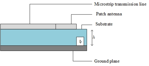
Figure 1: Microstrip patch antenna
The data depicted in Figure 1 suggests that the projected design produces a noteworthy increase in the dispersion of stimulated surface current in the core area of the emitting patch, as well as a substantial enhancement in the overall stimulated patch surface currents. The surface current changes when we alter the form of the ground channel, altering the return current on the radiating patch. This alteration in the surface current also affects the radiation pattern and frequency of operation. Therefore, we may miniaturise the antenna by merely changing the ground plane; if we want to run the antenna at a different frequency, we do not need to alter the antenna. The frequency of operation is reduced by changing the ground plan, allowing the same antenna to operate at a lower frequency.
Coaxial feed to microstrip antennas
The coaxial feed, commonly referred to as the probe feed, is still a frequently used technique for supplying power to microstrip patch antennas. This feeding technique's adaptability in establishing impedance matching is one of its standout characteristics. Antenna performance can be fine-tuned by positioning the feed in a suitable spot inside the patch. Its popularity has been boosted by its versatility, which is a major strength. It's important to keep in mind that longer probes may result in higher inductive input impedance, especially for substrates with thicker dielectric layers. This realization has led to the development of unique techniques for optimizing and regulating the input impedance to resolve matching problems. The coaxial feed method frequently uses thicker dielectric substrates to increase bandwidth. This method, meanwhile, may provide issues with spurious radiation and matching. To get beyond these limitations, researchers are continuously investigating cutting-edge substrate designs and dielectric materials. Figure 2 displayed the coaxial probe feeding technique.
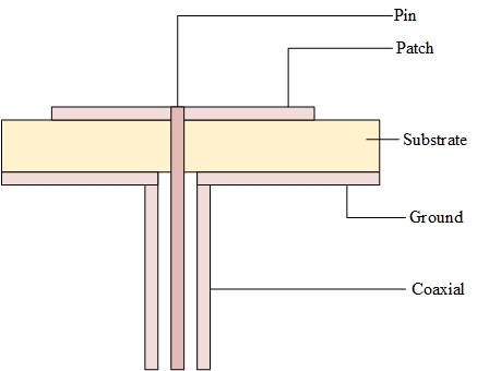
Figure 2: Coaxial feed
Multilayer Micro strip Antenna
A multi patch micro strip antenna is one that has more than one patch covering the dielectric substrate. Multi patch Micro strip antenna gives engineers who are primarily RF/microwave circuit designers fundamental knowledge on patch antenna design and operation. Low profile antennas may be deemed indispensable in high-performance missile, spacecraft, airplane, and satellite applications wherein crucial factors such as size, weight, cost, performance, and aerodynamic profiles necessitate their employment. Multi patch Micro strip antennas are employed to satisfy these needs. A ground plane is established by joining a continuous multi-metal layer to the opposing side of the substrate, while the antenna element pattern is designed via the etching of a metal trace that is attached to an insulating dielectric substrate. This method produces narrowband, broad beam antennas. Figure 3. depicts a schematic representation of a multilayer patch antenna.
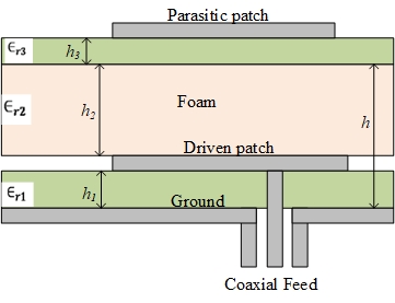
Figure 3: Schematic representation of a multilayer patch antenna
Antenna Design Specifications
Frequency of operation
The term "frequency of operation" ( in specifications for antenna design denotes the precise frequency at which the antenna is intended to function at its best. It is a crucial factor in determining how well the antenna will function and if it will work with the intended application.
Height of dielectric substrate:
The MPA must be thin and lightweight to be employed in mobile devices. Therefore, 1.6 mm is chosen as the dielectric substrate's height.
Dielectric constant
The ratio of electrical energy stored in a substance to that kept in a vacuum is known as the dielectric constant. The substance performs better as an insulator and is less likely to absorb electrons, resulting in less loss, the lower the dielectric constant. FR-4 epoxy, which has 4.4 dielectric constant, was employed.
Design Steps of Microstrip Antenna
(i) Calculating the patch's width (W)
The Microstrip antenna's width is specified as
(1)
Where , . stands for the speed of light and represents the resonance frequency.
(ii) Effective dielectric constant calculation
Fringing phenomena induces an electrical broadening effect of the Microstrip line, rendering it wider than its actual physical dimensions. This is attributed to the propagation of waves in both the substrate and air media, thus leading to an effective dielectric constant expressed as:
(2)
The substrate's dielectric constant is and is the effective dielectric constant. The width of the patch is , and the height of the dielectric substrate is .
(iii) Calculating the patch's length (L)
The effective length caused by fringing is given as follows:
(3)
Due to fringing, the patch's dimension was enlarged by on both sides as follows:
(4)
Hence, the patch's length is:
(5)
Proposed Multilayer Patch Antenna
The proposed decagon multilayer patch antenna has a ground plane of dimensions 144 x 84 mm with the thickness of 1.6 mm. For this design, FR-4 Epoxy with a thickness of 1.6 mm and a dielectric constant of 4.4 and a loss tangent of 0.002 is used as the dielectric material. The prototype's design exhibits a reduced dielectric constant which serves to enhance both its efficiency and bandwidth, whilst simultaneously augmenting the fringing field in proximity to the patch's edge and elevating the radiated power. In the simulation, the slight loss tangent was disregarded. The thickness of the substrate is another crucial design factor. The radiated power is increased by the low dielectric constant of the perimeter. HFSS is used to simulate the proposed antenna, and the outcomes of the simulation are obtained. The air gap serves as a substrate for a dielectric with a dielectric constant of 1. In this case, the proposed antenna is multilayer and comprises of a copper ground plane, an air gap with a height of 8 mm, and a copper layer. The antenna's radiative characteristics are greatly influenced by the substrate, which is an integral part of the antenna. In the process of substrate selection, several factors are considered. These include dielectric constant, thickness, stiffness, and loss tangent. Each of these attributes has a significant impact on the substrate selection process. To facilitate the phenomenon of fringing and, as a consequence, radiation, it is of utmost importance to minimize the dielectric constant. Furthermore, the selection of a thicker substrate is highly recommended as it significantly enhances the impedance bandwidth. The utilization of a thick substrate would result in a decrease in accuracy, as the majority of microstrip antenna models rely on a slender substrate approximation in their analysis. The proposed design uses coaxial feeding approach to match the impedance of the circuit with the antenna. The simulated multilayer antenna is shown in figure 4.
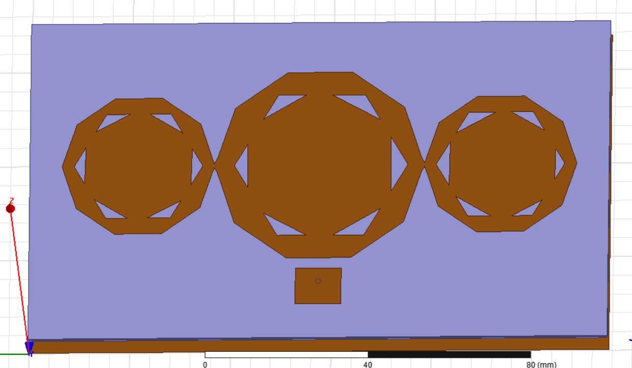
Figure 4: Proposed Multilayer antenna
Fabrication and Experimental Method
Fabrication Process
Numerous modern techniques can be used to create multilayer decagon-shaped microstrip antennas. However, photolithography is at the foundation of these processes. A multilayer decagon-shaped microstrip antenna is made using the following procedure, which incorporates cutting-edge techniques:
Advanced Mask Generation
The simulated antenna structure was initially precisely transferred onto a clear film using Auto-Computer Added Drawing (AutoCAD). However, the simulated device's physical dimensions were exact matches to the AutoCAD design.
Cutting-Edge X-ray Lithography
X-ray lithography is employed for the crucial photo exposure stage because it offers deep-submicron resolution, making it the perfect option for pushing the limits of cutting-edge antenna designs. It took two minutes and 120 seconds to efficiently conduct this cutting-edge procedure.
Spray Development
The utilization of dry film photoresist as a replacement for liquid photoresist was a revolutionary transformation in the development process. This pioneering option significantly streamlined development and concurrently increased the precision in antenna pattern creation.
Advanced Plasma Etching
Wet chemical etching was replaced as we advanced by the introduction of sophisticated plasma etching. This approach speeds up the procedure and offers better control over the removal of exposed material.
Etching in Ferric Chloride
Electrochemical etching, a novel substitute for chemical etching was employed, to further push the limits of traditional etching. This technique provided finer control over the etching process, enabling us to achieve intricate antenna designs with unparalleled precision.
Modernized Probe Soldering
Finally, the ultimate device structure is assembled through the ingenious merger of both developed and underdeveloped PCB. The incorporation of foam spacers, meticulously crafted with a dielectric constant closely resembling that of air, effectively serves to isolate the two aforementioned circuit boards. The assembly process is completed by employing SMA connection, which ensures smooth connectivity within this flawless arrangement. The bottom, side and top view of the fabricated antenna are displayed in the figure 5 (a), (b) and (c).
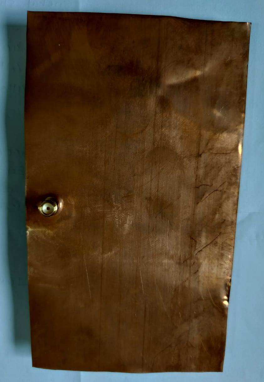
Figure 5(a): Fabricated antenna Bottom view
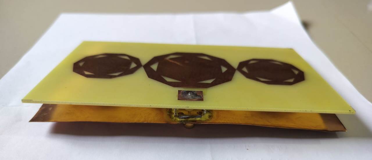
Figure 5(b): Fabricated antenna Side view
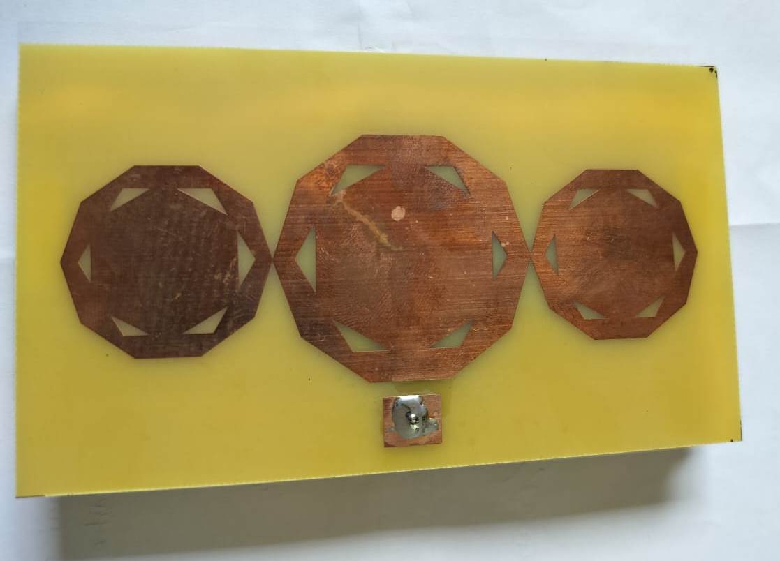
Figure 5(c): Fabricated antenna Top view
Software
(i) HFSS
The software tool, HFSS, which is used as the benchmark in the industry for simulating 3D full wave electromagnetic fields, operates on a Linux operating system that is based on a Debian foundation. Results for E and H field, current, S-parameter, and near- and far-field radiation are provided by HFSS. The automated solution method of HFSS, which only requires users to define geometry, material parameters, and the desired output, is essential to the tool's success as an engineering design tool. For the purpose of solving the problem, HFSS enables us to automatically construct a suitable, effective, and precise mesh.
Hardware
(i) Vector Network Analyzer
A versatile electronic test tool called a VNA is used to evaluate the performance of RF and microwave components and devices. It has the ability to examine the operation of devices including cables, amplifiers, filters, and antennas. The Return Loss, VSWR, and Bandwidth characteristics, which are essential for describing the performance of RF and microwave systems, are just a few of the important factors that the VNA measures. The VNA setup of this work is shown in the figure 6.

Figure 6. Experimental set up with VNA
Antenna parameters
The performance of a microstrip antenna is often assessed through the design and study of several variables. Some of these variables include antenna gain, return loss, antenna efficiency, VSWR, bandwidth, and directivity.
Antenna Gain
Antenna gain is a measurement of the increase in power density in a given direction in comparison to an isotropic radiator. It is typically expressed in decibels relative to isotropic (dBi). A more concentrated radiation pattern is indicated by a higher antenna gain.
(6)
Where the intensity of a given direction is denoted as and the input power is the .
Directivity
The parameter that quantifies the relative magnitude of a radiation's power in a particular direction with respect to its total power is formally referred to as directivity. It evaluates the antenna's ability to concentrate the emitted energy in a certain direction. A more targeted radiation pattern is indicated by a higher directivity.
(7)
Where is the radiation intensity and is the radiation power.
(iii) Radiation pattern
The radiation pattern of an antenna is a depiction, either mathematically or graphically, of its radiation characteristics in relation to its placement.
(iv) VSWR (Voltage Standing Wave Ratio)
A measurement of an antenna's ability to reflect electromagnetic waves is called VSWR. It computes the difference between the maximum and minimum amplitudes of the standing wave. Poor impedance matching between the antenna and transmission line is indicated by a high VSWR.
(8)
Where and are the minimum and maximum amplitudes of the standing wave.
(v) Return loss
Return loss is the measurement of the power that an antenna reflects back to a transmission line. It is calculated using the incident power to reflected power ratio. When the return loss is higher, impedance matching is improved and signal loss is reduced.
(9)
(vi). Antenna Efficiency
Efficiency is the rate at which an antenna can transform electrical energy into electromagnetic radiation. By dividing the input power by the output power, it is calculated. Less power loss in the antenna is indicated by a higher antenna efficiency. (10)
Where is the input power and the radiated power is the .
Results and Discussion
In this section, the results attained from the simulated and fabricated antenna are discussed. For the proposed antenna, the antenna's directivity, radiation pattern, VSWR, and return loss are all examined. Through simulation using the HFSS, the proposed multilayer antenna is created.
Simulation analysis
The measure of power dissipated to the load without being reflected back is denoted by the return loss. Similar to VSWR, return loss serves as a measurement of how well the transmitter and antenna have been matched. The ideal return loss value is less than -10dB, which corresponds to a VSWR of under 2. The figure 7 shows the simulated result of return loss.
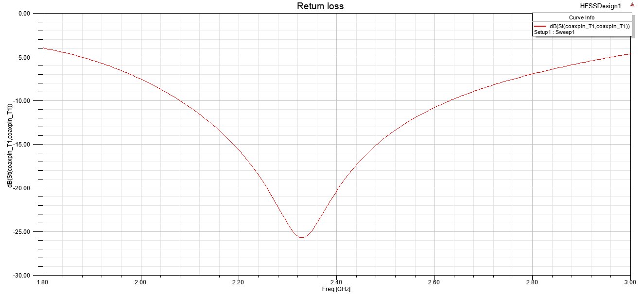
Figure 7: Simulated result of return loss
Figure 7 illustrates return loss of -25.6611 dB at a frequency of 2.328GHz, demonstrating the effectiveness of the proposed multilayer antenna.
An antenna's bandwidth is the spectrum of frequencies that can be utilized on either side of the center frequency. To measure an antenna's utilization of the necessary frequency range, one approach is to calculate its VSWR and Return Loss.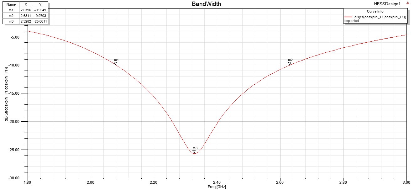
Figure 8: Bandwidth
The antenna has an operational frequency range of 2.07 GHz to 2.63 GHz and a bandwidth of roughly 551.5 MHz, making it ideal for wideband applications, according to the simulated S parameter plot in Figure 8.
The return loss will become considerably harsher and more unreliable if VSWR is high. It is believed that VSWR is allowed up to 2 in practical applications because the return loss would be around 10 dB. The simulated VSWR result is depicted in the figure 9
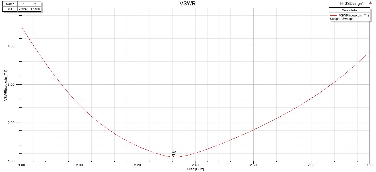
Figure 9: VSWR simulation result
Figure 6 shows that the VSWR value is 1.1106. The antenna is better suited when the VSWR value is lower. The value is smaller but more than the lowest VSW R value of one, according to the simulated VSWR plot.
The radiation pattern is another element that describes an antenna structure's radiation characteristics and sets one antenna apart from another. It is an antenna's far-field plot that is described using spatial coordinates. A basic aspect of an antenna is its radiation pattern, which shows how the aerial disperses energy in space. The values of phi and theta are put in risk by this radiation pattern. The figure 10 depicts the radiation pattern of the simulated antenna.
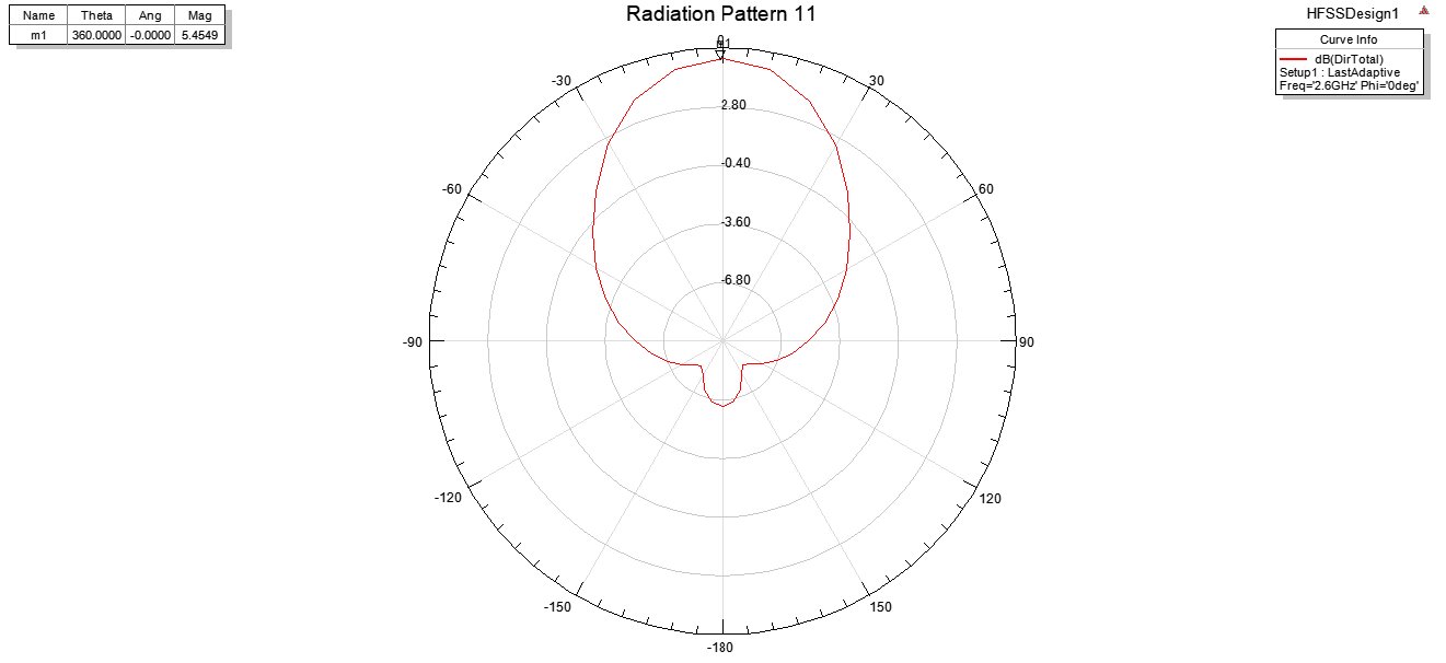
Figure 10: Simulated antenna radiation pattern
The gain and directivity of the design are shown in Figure 11 (a) and (b). The term "gain" is commonly utilized to denote the capacity to concentrate energy towards the desired direction in order to generate radiation that is efficient. The gain, in turn, is reliant on the antenna's efficacy and directivity. To receive or transmit electricity, it is advised to maximise the radiation pattern in a specific direction. The directivity of an antenna is characterized by the proportion of its radiation intensity in a particular direction to its total average radiation intensity. The geometry of the radiation pattern has a significant impact on the directivity.
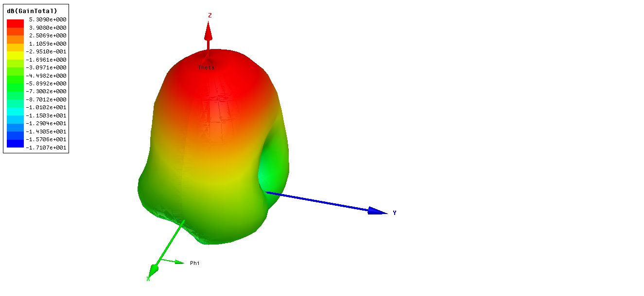
Figure 11 (a): Gain of the simulated antenna
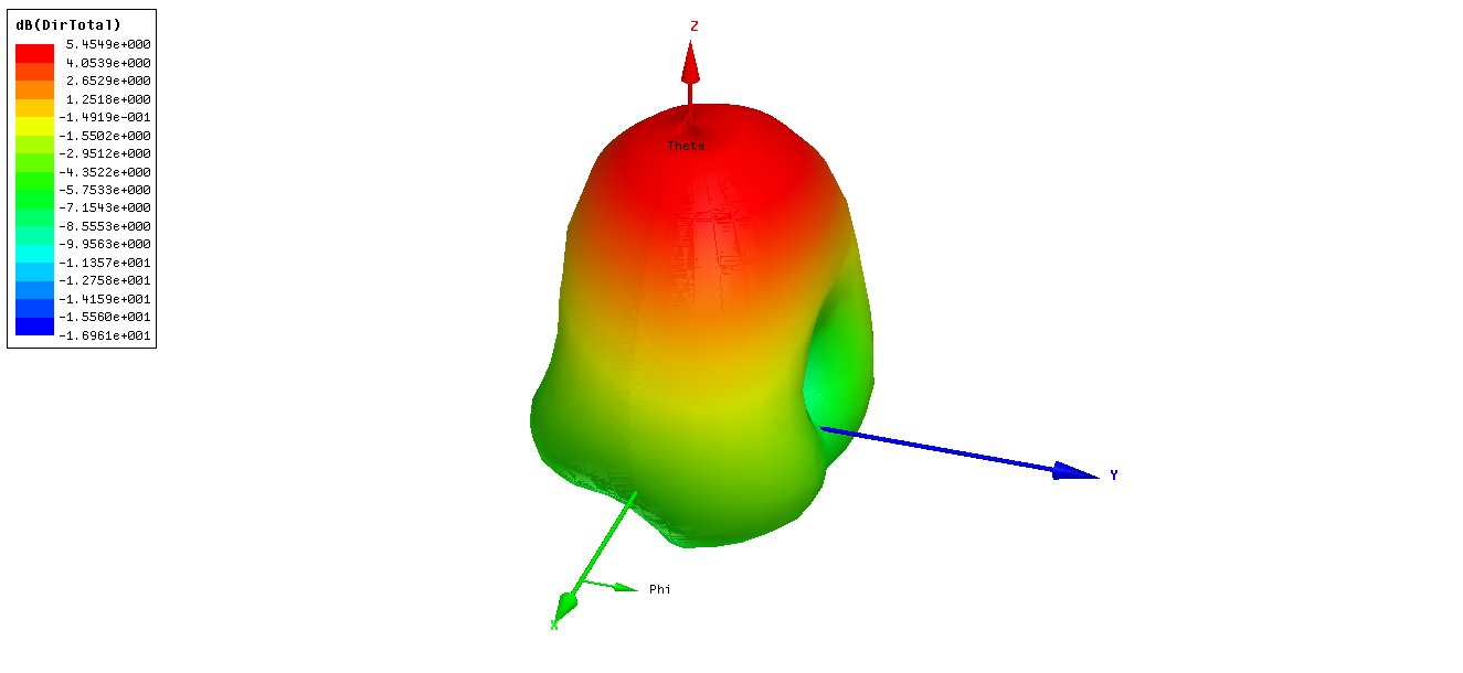
Figure 11 (b): Directivity of the simulated antenna
From the figure it is demonstrated that the gain and directivity of the simulated antenna are 5.3090 and 5.45 Db.
Comparison of the proposed and existing works
Table 2 shows the comparison analysis for the proposed and the existing multilayer microstrip patch antenna based on the values of return loss, frequency, bandwidth, gain and VSWR.
Table 2: Comparison table for proposed and existing work
Ref | Frequency (GHz) | Return loss (dB) | Bandwidth (MHz) | VSWR | Gain |
16 | 2.074 | -24.974 | 350 | 1.1205 | 5.2906 |
20 | 2.47 | -36.49 | 202.5 | – | 4.21 |
21 | 2.25 | -13.521 | 400 | – | 7.07 |
25 | 5.92 | -15.82 | 200 | 1.2 | 1 |
27 | 2.466 | -18.172 | 227 | 1.280 | 6.51 |
Proposed | 2.328 | -25.61 | 551.5 | 1.1106 | 5.309 |
Experimental Analysis
The experimental method results are analysed via VNA and the measured results are illustrated in this section. The return loss, bandwidth, VSWR and smith chart are examined for the fabricated antenna. The return loss and bandwidth outcomes are demonstrated in the figure 12. The measured VSWR is shown in the figure 13.
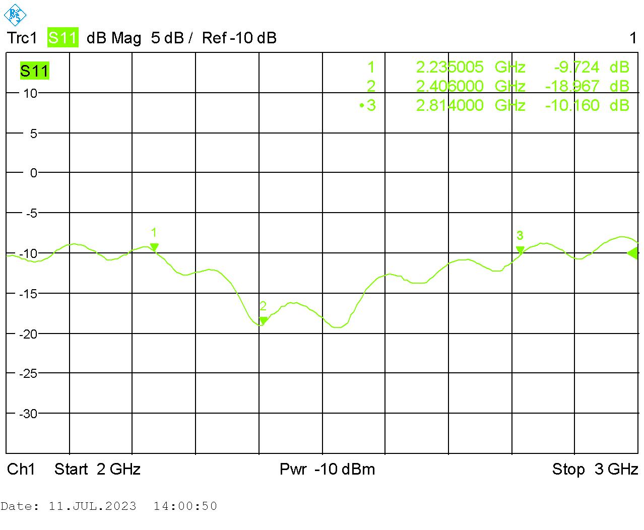
Figure 12: Return loss and Bandwidth
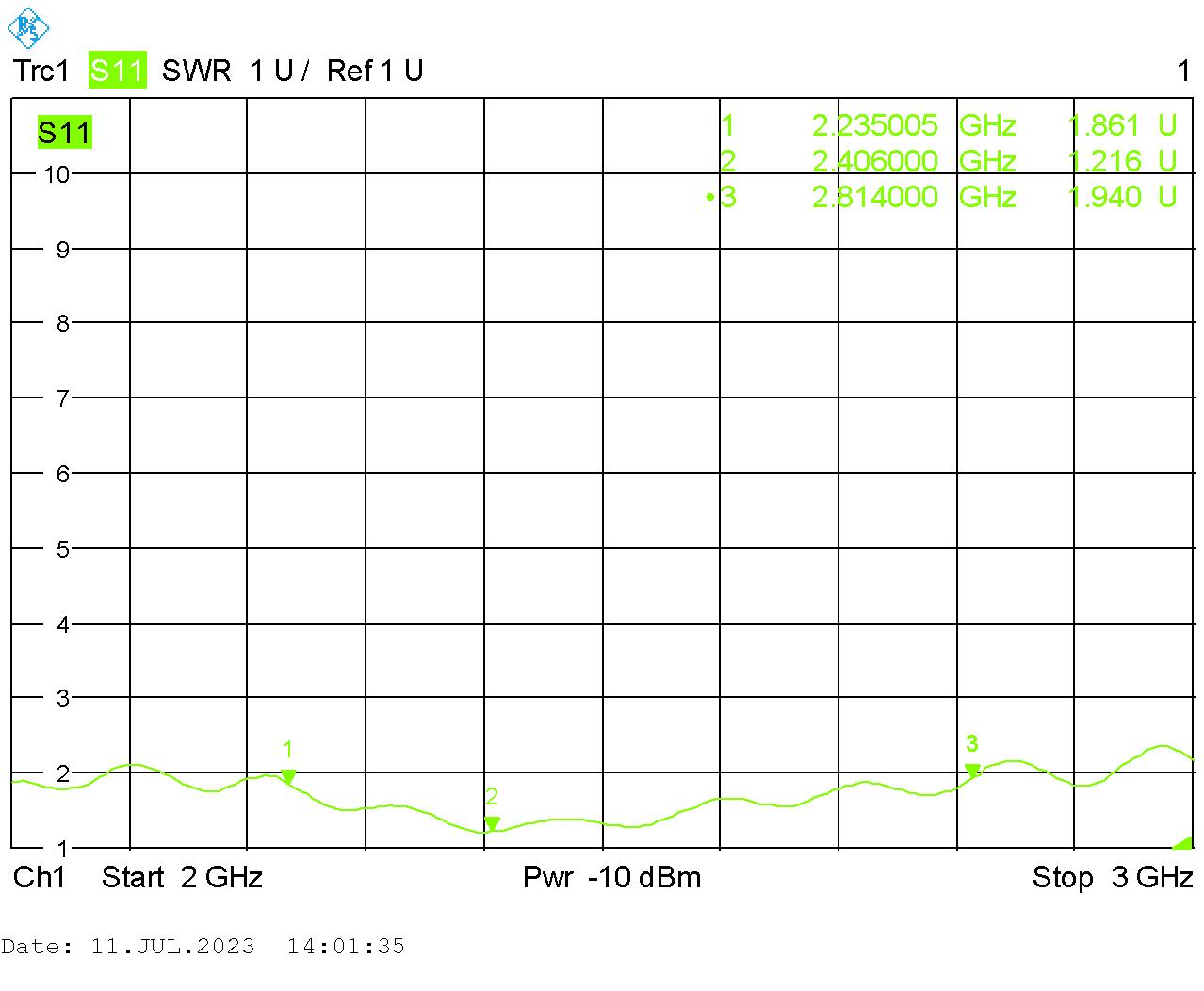
Figure 13: Experimental VSWR
The Smith Chart is a tool utilized for the purpose of representing the impedance of a physical antenna as measured on a VNA. Smith Charts are considered to be a crucial tool in the field of electrical engineering owing to their ability to aid in impedance matching. The measured Smith chart for fabricated antenna is displayed in the figure 14.
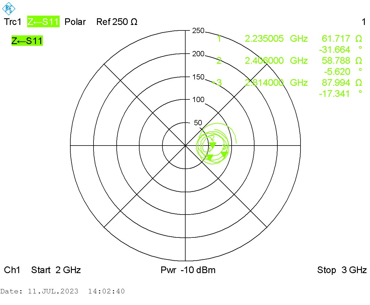
Figure 14: Smith chart
The utilization of the Smith Chart is highly advantageous in effectively demonstrating the alterations in impedance of a transmission line and antenna system with respect to frequency. Smith Charts are a useful tool for better understanding transmission lines and their behaviour from an impedance perspective. The complete experimental and backend setup of anechoic chamber is shown in figure 15 (a) and (b).

Figure 15 (a) Experimental setup in Anechoic chamber

Figure 15 (b) Experimental Backend Setup
Metal walls in an anechoic chamber protect our equipment from stray radio transmissions. Special RF absorbing materials are employed to cover the chamber's inner walls in order to reduce undesired reflections. Accurate repeatable measurements are made possible by protecting the test area from outside interference and minimizing wave reflection off the walls. This effectively replicates being inside an indefinitely big room. Foam pyramids filled with conductive carbon are frequently used to cover the inside surfaces of anechoic chambers. With low wave reflection, the tapering shape of the pyramid’s transitions radio waves from the air to the lossy carbon used in the construction of the pyramids. The radiation pattern of a decagonal antenna is typically examined in an anechoic chamber to determine its performance. Anechoic chambers are specialized testing settings used to measure and analyse antenna radiation patterns. In order to create a controlled environment for accurate measurements, it is intended to reduce reflections and outside interference. The antenna can be turned and tested at different angles in an anechoic room to provide a thorough radiation pattern. Figure 16 (a) and (b) illustrated the experimental and reading setup for anechoic chamber.

Figure 16 (a) Experimental reading for Anechoic chamber
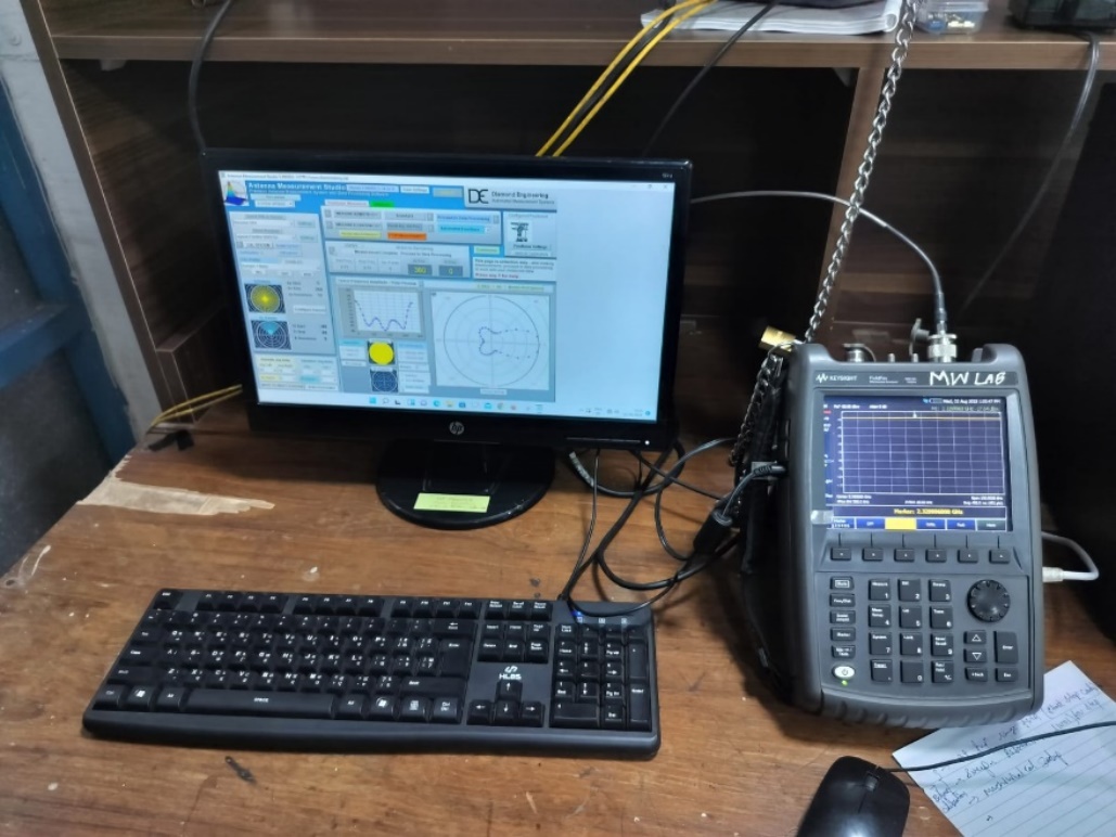
Figure 16 (b) Reading setup for Anechoic chamber
Conclusion
In this study, a multilayer decagon-shaped microstrip patch antenna is proposed and examined with the goal of enhancing bandwidth for broadband applications. Several performance parameters, including bandwidth, gain, directivity, return loss, VSWR, and radiation pattern, were used to extensively evaluate the antenna's performance. The simulation results from the HFSS were validated through experimental measurements utilising a VNA. The outcomes show that the proposed antenna design successfully handles the issue of increasing bandwidth for broadband applications. The antenna outperformed traditional patch antennas by a wide margin with a phenomenal bandwidth of 551.5 MHz In contemporary communication systems that need larger data speeds, this increased bandwidth guarantees effective data transmission and reception. Additionally, the antenna's performance metrics show that it is appropriate for real-world broadband application implementations. A minimum amount of signal reflection and effective power transfer between the antenna and the feedline are guaranteed by the low VSWR of less than 1.5 at 2.328 GHz over the entire operational bandwidth. The antenna's capacity to focus and direct the radiation pattern, resulting in improved signal strength and coverage, is demonstrated by its attained gain of 5.45 dBi and directivity characteristics. Additionally, the antenna's low return loss of -25.61 dB indicates a strong impedance match, which lowers signal losses and boosts overall efficiency. To achieve reliable and high-quality wireless connection, this is essential. The proposed antenna design has a lot of promise for use in real-world broadband applications, such as wireless networks, satellite communication systems, and internet of things (IoT) gadgets. The results that have been presented help to progress multilayer antenna technology and open fresh opportunities for investigation and improvement in the area of high-performance antenna design.
References
Bendahmane, Z., Ferouani, S. and Sayah, C., 2020. High permittivity substrate and DGS technique for dual-band star-shape slotted microstrip patch antenna miniaturization. Progress In Electromagnetics Research C, 102, pp.163-174.
Krishnaveni, G. and Manimegalai, B., 2021. Efficient and optimized design of a stacked patch microstrip antenna for next generation network applications. Journal of Ambient Intelligence and Humanized Computing, 12, pp.4093-4099.
Bello, H., Nazifi, K.I. and Sadiq, S.M., 2023. Investigation and design methods of a compact patch antennas using 3-D MMIC for various applications. Global Journal of Engineering and Technology Advances, 15(03), pp.096-106.
Apriono, C., Mahatmanto, B.P.A. and Juwono, F.H., 2023. Rectangular Microstrip Array Feed Antenna for C-Band Satellite Communications: Preliminary Results. Remote Sensing, 15(4), p.1126.
Ossa-Molina, O. and López-Giraldo, F., 2022. A simple model to compute the characteristic parameters of a slotted rectangular microstrip patch antenna. Electronics, 11(1), p.129.
Gupta, N., Gill, N. and Maniraguha, F., 2022. Modeling and Performance Optimization of a Compact Three-Petalled Flower-Like Microstrip Patch Antenna for IoT Applications. Wireless Communications and Mobile Computing, 2022.
Gupta, N., Gill, N. and Maniraguha, F., 2022. Modeling and Performance Optimization of a Compact Three-Petalled Flower-Like Microstrip Patch Antenna for IoT Applications. Wireless Communications and Mobile Computing, 2022.
Behera, S.B., Barad, D. and Behera, S., 2020. A Small Form Factor Impedance Tuned Microstrip Antenna with Improved Gain Response. Progress In Electromagnetics Research M, 95, pp.13-23.
Karami, F., Rezaei, P., Amn‐e‐Elahi, A., Abolfathi, A. and A. Kishk, A., 2021. Broadband and efficient patch array antenna fed by substrate integrated waveguide feed network for Ku‐band satellite applications. International Journal of RF and Microwave Computer‐Aided Engineering, 31(9), p.e22772.
AL-Amoudi, M.A., 2021. Study, design, and simulation for microstrip patch antenna. International Journal of Applied Science and Engineering Review (IJASER), 2(2), pp.1-29.
Gaharwar, M. and Dhubkarya, D.C., 2023. X-band multilayer stacked microstrip antenna using novel electromagnetic band-gap structures. IETE Journal of Research, 69(4), pp.2015-2024.
Aneesh, M., Ansari, J. and Singh, A., 2014. Analysis of microstrip line feed slot loaded patch antenna using artificial neural network. Progress in Electromagnetics Research B, 58, pp.35-46.
Melouki, N., Hocini, A., Fegriche, F.Z., PourMohammadi, P., Naseri, H., Iqbal, A. and Denidni, T.A., 2022. High-gain wideband circularly polarised Fabry–Perot resonator array antenna using a single-layered pixelated PRS for millimetre-wave applications. Micromachines, 13(10), p.1658.
An, W., Tian, X., Wang, J. and Wang, S., 2023. Low-Profile Dual-Polarized Double-Layer Microstrip Antenna for 5G and 5G Wi-Fi. Micromachines, 14(5), p.942.
Sheng, X., Lu, X., Liu, N. and Liu, Y., 2022. Design of Broadband High-Gain Fabry–Pérot Antenna Using Frequency-Selective Surface. Sensors, 22(24), p.9698.
Jothilakshmi, P., Maveerapandi, P., Prasanna, D.L. and Vaishnavi, V., 2019. Simulation and Analysis of Aperture Coupled Patch Antenna for S-Band Communication. Simulation, 5(8), pp.103-109.
Venkatesh, P., Ranjana, V., Rohini, S. and Sangareswari, A., 2019. Design of miniaturized printed antenna for Wi-Fi application. International Journal of Applied Engineering Research, 14(6), pp.1-4.
Bansode, P., 2019. 2X8 Multilayer microstrip patch array antenna for C-Band radar micro-SAR. arXiv preprint arXiv:1903.00224.
Srivastava, H. and Tiwari, U., 2019. Design, simulation and analysis of rectangular and circular microstrip patch antenna for wireless applications. International Journal of Recent Technology and Engineering (IJRTE), 8(4), pp.2277-3878.
Ajay, V.G., Mathew, T., Prasad, N.K. and Sarma, M.S.S.R.K.N., 2020. Truncated Microstrip Patch Antenna with DGS Based on Double Looped CSRR Arrays for Enhancement of Bandwidth. Indonesian Journal of Electrical Engineering and Informatics (IJEEI), 8(3), pp.593-601.
Hemanth, D.J., 2020. Design of Compact High Gain Multilayer Stacked Patch Antenna. Intelligent Systems and Computer Technology, 37, p.463.
Anandkumar, D. and Sangeetha, R.G., 2020. Design and analysis of aperture coupled micro strip patch antenna for radar applications. International Journal of Intelligent Networks, 1, pp.141-147.
Mishra, M.T.S.S. and Chourasia, B., 2021. Design and Analysis of L Band Microstrip Patch Antenna for Global Navigation Satellite System.
Sagar, P.P., Rajesh, V., Altahan, B.R., Venkateswararao, M., Ahammad, S.H., Smirani, L.K., Hossain, M.A. and Rashed, A.N.Z., 2023. Design and Analysis of Rectangular Circularly Polarized Array Antenna for Flexible IoT Applications. Wireless Personal Communications, 130(2), pp.1257-1275.
Hannan, M., Shanmuganantham, T., Shahid, M., Sindhanaiselvi, D., Kumar, S.A. and Srihari, G., 2023. High Gain Multilayered Microstrip Patch Antenna for C Band Applications. International Journal of Microwave & Optical Technology, 18(2).
Rathod, A.K., Sonkamble, R.G., Sharanabasappa, R.R., Mathpati, M.S. and Bhakar, M., 2018. Comparative study to improve antenna parameters of multilayer microstrip patch antenna. In Techno-Societal 2016: Proceedings of the International Conference on Advanced Technologies for Societal Applications (pp. 433-445). Springer International Publishing.
Rathod, A.K., Bhakar, M.M., Mathpati, M.S., Chougule, S.R. and Sonkamble, R.G., 2021, May. Bandwidth Improvement of Multilayer Microstrip Patch Antenna by Using Capacitive Feed Technique for Broadband Applications. In Techno-Societal 2020: Proceedings of the 3rd International Conference on Advanced Technologies for Societal Applications—Volume 1 (pp. 23-30). Cham: Springer International Publishing.
Cite This Work
To export a reference to this article please select a referencing stye below:

Academic Master Education Team is a group of academic editors and subject specialists responsible for producing structured, research-backed essays across multiple disciplines. Each article is developed following Academic Master’s Editorial Policy and supported by credible academic references. The team ensures clarity, citation accuracy, and adherence to ethical academic writing standards
Content reviewed under Academic Master Editorial Policy.