
Environmental Toxicology
circuit designTextbook
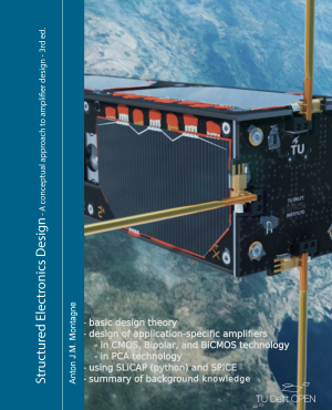
Structured Electronics Design: A Conceptual Approach to Amplifier Design, 3rd ed.
Not rated yetRate this bookAnton J. M. Montagne's Structured Electronics Design develops a conceptual, specification-led approach to amplifier design. This guide covers the introductory framework, fourteen application-specific amplifier chapters, and four background chapters in the third edition. It connects models, devices, noise, feedback, dynamics, compensation, multistage architecture, and biasing with focused analytical and simulation tasks.
Free reading is available at the official source. Opens in a new tab.
 Free
About this book
Anton J. M. Montagne's Structured Electronics Design develops a conceptual, specification-led approach to amplifier design. This guide covers the introductory framework, fourteen application-specific amplifier chapters, and four background chapters in the third edition. It connects models, devices, noise, feedback, dynamics, compensation, multistage architecture, and biasing with focused analytical and simulation tasks.
Chapter-wise summaries and study tasks
Introduction: systems engineering and structured electronics design
Structured electronics design connects an information-processing requirement with a circuit whose performance can be explained and evaluated. The introduction uses systems-engineering ideas to separate function, specifications, implementation choices, constraints, and cost. A circuit topology is a candidate means rather than the starting definition of the problem. Modeling supports decisions at different levels of detail, with information quality and source-to-load behavior central to the analysis. The book's structured approach combines conceptual reasoning, symbolic relationships, and numerical tools instead of treating simulation as a substitute for understanding. Establish what success means and which assumptions make an abstraction useful before optimizing component values.
Study task. Write a fictional amplifier brief with signal, source, load, accuracy, noise, bandwidth, operating conditions, and constraints. Separate required behavior from a preferred topology and define an evaluation plan.
Modeling and specification of amplifiers
Amplifier specification starts with what the source and load require at their ports. Voltage, current, and transfer relationships define different ideal amplifier types, while impedances and grounding arrangements affect real signal transfer. Ideal behavior establishes a reference; nonideal models add isolation errors, noise, nonlinearity, and dynamics. Available power gain and source-to-load performance answer related but distinct questions. A large unloaded gain does not establish that the intended load receives an accurate signal. Specifications should therefore describe conditions, units, limits, and relevant frequency or amplitude ranges. Select a model detailed enough to expose the error that matters.
Study task. Model a fictional source-amplifier-load system and calculate a loading effect. Create separate ideal and nonideal specifications and explain which measurement would test each requirement.
Amplification Mechanism
Amplification uses an active device and supplied energy to control signal transfer. Operating point and linearization connect a nonlinear device characteristic with a local small-signal model. Two-terminal and multi-terminal descriptions reveal how control and output quantities interact. Bias sources establish the conditions under which useful amplification occurs; they are not merely extra components added after the signal analysis. Distinguish incremental gain from large-signal behavior and available power from a visually large voltage. A local linear approximation requires a justified range and cannot explain clipping or every transient by itself.
Study task. Linearize a hypothetical device characteristic around two operating points. Explain how the bias choice changes the local model and why small-signal gain does not establish large-signal performance.
Active Devices
Active-device models balance physical detail, parameter availability, and the question being answered. Bipolar, junction-field-effect, and MOS transistors require different descriptions, and simplified hand models serve a different purpose from more detailed simulation models. Numerical output depends on model validity, parameter conditions, and implementation. Matching one characteristic does not prove that noise, frequency response, or behavior across bias and temperature is equally accurate. The chapter develops device reasoning as a basis for design rather than a catalog of preferred components. Compare a simplified calculation with simulation to understand discrepancies, not merely select the result that meets the target.
Study task. Compare a source-supported simplified transistor model with a detailed model for a fictional bias range. Identify which predicted characteristics are trustworthy and which need additional parameters or validation.
Basic amplification: CS stage
The common-source stage serves as a basic amplification building block. Intrinsic instantaneous, dynamic, large-signal, and noise behavior establish different aspects of performance, while source and load connections change the realized result. Transconductance, impedances, parasitic effects, and signal amplitude interact rather than supply independent knobs. Noise optimization depends on the source and the relevant frequency range, not only on maximizing a device parameter. A stage can improve one metric while worsening power, bandwidth, or distortion. Trace the source-to-load signal and noise paths and distinguish device limitations from the consequences of the chosen external connections.
Study task. Analyze a fictional CS stage for gain, loading, noise, and a dynamic limitation. Change one bias or sizing assumption and explain the resulting trade-off rather than report only improved gain.
Balancing techniques
Balancing uses paired or complementary structures to shape unwanted contributions, including selected nonlinear or common effects. Symmetry can support cancellation, but the result depends on the quantity, connection, device behavior, and matching assumptions. Anti-series, anti-parallel, and complementary arrangements are not interchangeable simply because they use two devices. The chapter connects these structures with balanced CE and CS stages. A cancellation shown under ideal symmetry should be tested against mismatch and operating variation. Keep the desired signal path visible and examine whether a technique introduces costs in noise, complexity, headroom, or available resources.
Study task. Compare two fictional balanced arrangements, identifying the contribution intended to cancel and the assumptions required. Introduce a mismatch and explain which residual effect returns.
Design of feedback amplifier configurations
Feedback configuration design determines how an output-related quantity is sensed and compared with an input. The selected arrangement should implement the required transfer and port behavior rather than inherit an arbitrary op-amp circuit. Direct and indirect sensing or comparison introduce different possibilities. Feedback networks and controller choices interact with noise, power, and source-load conditions. The distinction between negative and positive feedback depends on the full loop and conventions. A feedback label alone does not establish stability or accuracy. Follow the stepwise design logic and evaluate the resulting configuration against the original specifications before selecting detailed components.
Study task. Choose a feedback configuration for a fictional transfer requirement. Label sensed and compared quantities, intended port behavior, loop sign conventions, and the checks needed before claiming a working design.
Application and specification of operational amplifiers
Operational-amplifier applications require interpreting device characteristics within the proposed circuit. Idealized models are useful references, but finite transfer, port properties, noise, bias, offset, common-mode behavior, supply sensitivity, and large-signal limits can affect performance. A specification measured under one condition may not apply unchanged to another source, load, supply, or frequency. Macro models provide selected behavior rather than an assurance that every effect is represented. The chapter connects characterization with feedback configuration choices. Read a specification as a conditional statement and identify the system-level error to which it contributes.
Study task. Audit a fictional op-amp application against a set of conditional specifications. Separate small-signal bandwidth, slew behavior, offset, and noise, and identify an effect a chosen macro model may omit.
Introduction to amplifier biasing
Biasing establishes the operating conditions needed for amplification and the signal range the circuit can accommodate. DC and AC coupling, sources derived from supplies, common-mode requirements, and error-reduction techniques need coordinated treatment. Supply and resistor tolerances combine with controller imperfections to create a bias-error budget. Negative feedback, auto-zero concepts, and modulation-related approaches address different problems and introduce their own conditions. A nominal operating point does not establish adequate margin under variation. Separate an error that shifts a baseline from noise or distortion, and evaluate the available headroom after the bias arrangement is included.
Study task. Create a fictional bias-error budget with supply, resistor, and controller contributions. Test operating margins under variation and explain which error-reduction approach addresses which source.
Modeling of negative feedback circuits
Models of negative-feedback circuits connect a physical network with quantities such as asymptotic transfer, loop gain, direct transfer, and impedances. Black's model is useful under appropriate conditions, while a more complete representation helps expose limitations of an oversimplified loop picture. Selecting a loop-gain reference is an analytical choice that must be made consistently. Loading and multiple paths can complicate a casual claim that closed-loop gain is determined solely by the feedback network. Use symbolic reasoning and carefully defined tests to relate the model to the circuit. A simulation probe should measure the intended quantity without unintentionally changing the operating network.
Study task. For a fictional feedback circuit, identify the reference used for loop analysis and distinguish asymptotic transfer from finite-loop error. Explain how loading or a direct path could alter a simple feedback estimate.
Amplifier performance and controller requirements
Performance requirements translate the desired amplifier behavior into demands on the controller and feedback arrangement. Static error, nonlinearity, bandwidth, and dynamic range create interacting constraints. A high loop gain in one region does not guarantee suitable behavior across every frequency or signal amplitude. Poles and zeros shape the servo response and must be interpreted in relation to the complete transfer. The chapter supports a design process that derives requirements rather than selecting a controller by one favorable headline value. Identify which imperfection dominates each operating condition and whether improving it transfers the limitation elsewhere.
Study task. Translate fictional accuracy, distortion, and bandwidth targets into a controller-requirement outline. Identify conflicting demands and explain which assumptions support the proposed allocation of error and gain.
Frequency compensation
Frequency compensation shapes dynamic behavior so that a feedback amplifier meets stability and response requirements. The chapter examines approaches including phantom-zero compensation and pole splitting, with attention to where a compensating element is implemented. A change that improves a loop characteristic can also alter noise, loading, signal transfer, or available bandwidth. The Miller effect is part of this interaction rather than a universal explanation for every pole movement. Compensation should follow a stated model and design objective. Verify the resulting source-to-load behavior and relevant operating cases rather than equate one margin or a smooth step response with complete success.
Study task. Compare two conceptual compensation choices for a fictional loop model. State the expected pole-zero effect, verify closed-loop response, and examine at least one cost in noise, loading, or bandwidth.
Local feedback stages
Local-feedback stages implement feedback within a building block before it is placed in a larger amplifier. Common-drain and common-gate arrangements, passive-feedback stages, balancing, and indirect structures such as mirrors have different port and transfer properties. Their names alone do not establish how they will behave in the surrounding network. Local feedback can modify impedance and other performance, while consuming headroom or adding noise and dynamic effects. Analyze the stage under its actual source, load, and bias conditions. The benefit of modular design depends on preserving the assumptions used when the module was characterized.
Study task. Compare two fictional local-feedback stages for a specified port requirement. Include loading, headroom, noise, and a dynamic concern, and explain what must be rechecked when the stage is embedded in a larger circuit.
Multi-stage Feedback Amplifiers
Multistage design allocates tasks among stages and interconnections. Input-stage choices may be dominated by source and noise requirements, while output-stage choices depend strongly on load and signal delivery. The number of stages, their gain and dynamics, and connections to the feedback network affect the achievable overall result. Cascode and local-feedback techniques provide options with conditions and costs. A chain of individually satisfactory stages is not automatically a satisfactory amplifier because loading, bias, poles, and large-signal limits interact. Follow the structured sequence from requirements to architecture and then evaluate the integrated design.
Study task. Create a fictional multistage architecture with a responsibility assigned to each stage. Track loading, noise, poles, signal range, and feedback interaction across interfaces and identify the most fragile assumption.
Amplifier Biasing
The later biasing chapter develops a structured approach to implementing operating conditions in an integrated amplifier. Initial schemes, passive biasing elements, CE or CS stages, local-feedback stages, and cascodes require attention to signal preservation as well as DC feasibility. An acceptable bias point must survive tolerances and environmental variation within the design assumptions. Bias networks can add noise, loading, and frequency dependence. Separate the ideal bias function from the nonideal elements used to realize it, then check interaction with the completed signal path. Treat biasing as part of the design logic rather than a final exercise in forcing a simulator to converge.
Study task. Add a documented bias scheme to a fictional multistage design. Check nominal and varied operating points and explain effects on signal transfer, headroom, noise, and the original specification.
Signal Modeling (selected topics)
The signal-modeling background provides language for representing information-bearing quantities in forms useful for analysis. Time and frequency descriptions reveal different features, and model assumptions about stationarity, bandwidth, or composition determine what a calculation means. A convenient sinusoidal test is not a complete description of every real input. Connect amplitude, spectral content, power, and units with the physical source. Use the background to clarify earlier design arguments rather than apply transformations as unexplained algebra. Distinguish a representation choice from a change in the signal itself.
Study task. Describe a fictional source in both time and frequency terms. Explain which amplifier test each description supports and what information would be lost by using only a single test frequency.
System Modeling (selected topics)
System-modeling concepts connect input-output relationships, dynamics, and approximations. Linearization and transfer descriptions are conditional tools, not universal statements about a physical circuit. Poles, zeros, and response representations support reasoning about behavior within the model's range. Interconnection can change the apparent properties of a block, especially when an assumed isolation does not hold. A model should state operating conditions, variables, and omitted effects. Returning to these foundations helps distinguish an analytical limitation from an unexpected physical effect when calculation and simulation differ.
Study task. Write a system-model statement for a fictional amplifier block, listing assumptions and operating range. Identify one interconnection that invalidates an isolation assumption and explain how the model must change.
Network Theory (selected topics)
The network-theory background develops selected tools for analyzing interconnected electrical elements. Circuit laws and network representations require consistent reference directions and definitions. Two-port or matrix descriptions can make source, load, and internal relationships easier to organize, but their parameters still depend on conditions and conventions. A correct algebraic manipulation may be physically misinterpreted if port variables or sign conventions change unnoticed. Use small networks to verify the meaning of a parameter before relying on a large symbolic expression. Network analysis supports design decisions when it exposes which element or connection drives a result.
Study task. Analyze a small fictional two-port with explicit reference directions, connect a source and load, and verify the transfer independently using circuit equations.
Noise in electronic systems
Noise analysis distinguishes random fluctuation from deterministic offset or distortion and connects device sources with system-level performance. Spectral density, bandwidth, transfer, and correlation assumptions matter when combining contributions. An input-referred quantity depends on the transfer used to refer it, and a density is not the same as total integrated noise. Source impedance and frequency range influence which contributor dominates. A lower device-noise figure does not automatically produce a better complete design. State the model and measurement conditions, integrate over the relevant band, and avoid adding uncorrelated amplitudes as though they were deterministic signals.
Study task. Prepare a fictional noise budget with source, device, and network contributions. State units, bandwidth, transfer, and correlation assumptions, then identify which design change could reduce total noise and at what cost.
How to study this book
- Begin with source-to-load specifications, units, operating ranges, and an error budget before choosing a topology.
- Use simplified models to expose mechanisms, then compare with more detailed analysis and simulation under stated conditions.
- Keep small-signal, large-signal, noise, DC bias, and dynamic analyses distinct while checking their interactions.
- Document loop conventions, parameter origins, approximations, and limitations so that results are reproducible.
- Test variations in source, load, bias, components, and environment; meeting a nominal target alone does not establish a robust design.
- Use supervised or simulated exercises and appropriate engineering practice before implementing physical hardware.
Questions for reflection
- Which specification drives the architecture?
- Does the model include the effect being used to justify the decision?
- What improves when a parameter changes, and what becomes worse?
- Which module assumption fails after interconnection?
- Does the complete design meet requirements across the stated operating range?
Source edition and coverage
The guide follows the linked third-edition TU Delft source, including its introductory systems-design framework, Chapters 2-15 on amplifier design, and four selected-topic background chapters. It provides original orientation and study prompts rather than a replacement for the book's derivations, device models, or a validated hardware design. These are original study explanations and learning tasks. Read the complete book at the official source.
About access & copyright
This page provides book information and study material. Full-text access is provided by the original publisher or authorised source; a listing does not grant permission to republish the book.
Read our Library Access & Copyright policyExplore the contents
Check the chapters covered in this edition.
Visit the official source
See reading, preview or purchase options.
Save for later
Keep this textbook in your saved collection.
Reader ratings & reviews
Share your thoughts
Your review helps other students choose the right resources.
KEEP LEARNING
Your next great read
Chemistry
Vaccination Programmes
Vaccination Programmes
View Vaccination Programmes — bookRelativistic Quantum Mechanics
Relativistic Quantum Mechanics
View Relativistic Quantum Mechanics — bookAerospace Structures
Aerospace Structures
View Aerospace Structures — book Abelian number fields
Number Fields
View Number Fields — book Textbook
Agricultural Meteorology and Climatology
View Agricultural Meteorology and Climatology — book Language teaching and learning
In the Community: An Intermediate Reading and Writing Textbook
View In the Community: An Intermediate Reading and Writing Textbook — book Communication Studies
Technical Writing Essentials 2nd Edition
View Technical Writing Essentials 2nd Edition — book Language learning for academic, technical and scientific purposes
Technical Communication in Engineering: A Place-Based Approach
View Technical Communication in Engineering: A Place-Based Approach — book mathematical modelling