
Abstract
High-frequency operation in modern vehicles can produce electromagnetic interference (EMI), and wiring harnesses can act as both sources and recipients of unwanted coupling. Corrosion, ageing and deterioration may change cable performance after manufacture. This study examines automotive cable shielding through three-dimensional modelling in Ansoft HFSS and measurements of antilock braking system (ABS) and airbag cables at different deterioration levels. The simulation represents a conductor near a printed circuit board, while measurements use a semi-anechoic chamber and a network analyser. The results describe frequency-dependent coupling and differences among cable samples. The study also discusses the relationship between these observations and the emission limits illustrated from CISPR 25.
Keywords: Ansoft HFSS, Automotive,
Electromagnetic field, Shielding Effectiveness.
Introduction
Advances in electronics have increased the importance of controlling interference between devices. Electromagnetic interference is an unwanted disturbance that affects electrical or electronic performance. It can arise when signals from surrounding devices, or from another part of the same system, couple into the intended signal path and cause undesirable outputs or malfunction.
Electromagnetic compatibility (EMC) is the ability of equipment to operate satisfactorily in its intended electromagnetic environment without introducing unacceptable disturbances. Both emissions and immunity matter. Radio-frequency applications span approximately 3 kHz to 300 GHz and include navigation, broadcasting, mobile communications, GPS, Wi-Fi and satellite links. Interference control is relevant across these applications.
Increasing component density, operating speed and integration makes EMC design more demanding. Common control techniques include shielding, grounding, short routing and twisted pairs. Grounding and bonding provide suitable paths and connections for unwanted currents, while shielding limits electromagnetic coupling. Single-point, multipoint and hybrid grounding arrangements serve different design needs. A shield acts as a barrier between a source and a receiver; its effectiveness depends on the material, geometry, frequency and treatment of discontinuities.
Vehicle wiring harnesses can receive interference and radiate unwanted energy, potentially affecting electronic and safety systems. Shielding helps limit this coupling, but ageing, corrosion and deterioration can change its performance. This paper reviews shielding principles and enclosure effects, describes an automotive cable simulation, and presents measurements of ABS and airbag cables.
Literature Review
EMC testing considers whether equipment limits its emissions and withstands disturbances from its environment. Designers can reduce noise at its source through component selection and circuit design, or limit propagation through filtering and shielding. A suitably designed enclosure can reduce electromagnetic leakage and external coupling.
Circuit-level controls may need to be supplemented by shielding enclosures. An enclosure can limit both outgoing and incoming electromagnetic energy when its materials, connections and openings are appropriately designed. Figure 1 illustrates the role of a shield [1].
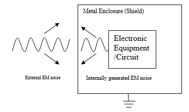
Figure 1: Role of Shield
A shield separates two regions and controls electromagnetic propagation between them. Shielding effectiveness compares an unshielded response with a shielded response under a defined measurement arrangement [2]. Holes, seams, slots and cable penetrations can reduce performance if they are not properly treated [3]. Practical equipment needs access, ventilation and interconnections, making the design of these openings an important part of enclosure shielding.
Electromagnetic shielding reduces transmission through a material or structure. Apertures, cables and wires can provide leakage paths when shielding is incomplete. The literature cited here reports differences between magnetic-field and electric-field leakage through apertures [3].
The number and size of apertures, enclosure geometry and material properties all influence shielding effectiveness. These features require careful assessment. A transmission-line method has been used to calculate the shielding of metallic enclosures with apertures and to examine the improvement obtained with a two-layer enclosure [4].
Electric vehicles contain extensive electrical and electronic systems. Finite-element tools have been used to study magnetic fields and exposure [5]. One cited estimate assigns cables, batteries and electronics approximately one quarter of the weight of a fully automated electric vehicle [6]. Long cable runs can support high-frequency emissions and coupling into low-voltage systems [7]. Energy storage and magnetic sensors are further topics in the electromagnetic assessment of electric and hybrid vehicles [8].
A coaxial transmission-line investigation examined the EMI shielding of stainless-fibre composites for automotive applications. The cited study reports improved shielding over a frequency range extending to 1.5 GHz compared with polypropylene composites, indicating potential applications in automotive and electronic components [9].
Interconnects between subsystems can also contribute to radiation. Connections that provide continuity at DC or low frequencies may behave differently at high frequencies. Changes in material or physical dimensions can introduce impedance mismatches and reflections. Previous work has examined low-frequency interference from vehicle cables [10], emissions and shielding design for high-voltage harnesses [11], vehicle-level numerical analysis [12], and electromagnetic topology models that represent a vehicle as interconnected subsystems [13].
A wiring harness bundles conductors carrying signals and electrical power. Its total conductor length can extend over several kilometres. Vibration, temperature, corrosion and ageing can cause deterioration. Earlier cable studies have considered EMC and crosstalk between bundles [14]. Another comparison reports better performance for shielded twisted-pair automotive Ethernet cables below 3 GHz and for shielded parallel-pair cables above 3 GHz [15].
Network, audio and safety-system cables can act as unintended antennas. A design may meet its initial emission requirements yet change during service as vibration, corrosion and ageing affect contacts and connections. These changes can influence shielding performance.
Corrosion changes metallic materials and their electrical properties; its rate depends on the materials and environment. Connector performance matters in automatic steering, braking and other vehicle control systems [16]. A cited harness investigation reports connector resistance reaching three times its initial value [17]. Maintaining conductivity and appropriate low-impedance connections therefore matters for shielding. Dissimilar metals can promote galvanic or other electrochemical reactions, and changes in cable impedance can affect emissions [18]. Multiconductor transmission-line modelling has also been used to analyse induced currents, with reported agreement between analytical calculations and HFSS simulations [19]. Cable position and termination impedance are additional influences on radiated emissions [20].
A circuit model for a lossy shielded cable used the method of characteristics to represent incident-wave effects. The cable was divided into uniform sections, and its current and voltage distributions were compared with other modelling techniques [21].
An earlier technical note by Bhuvaneswari, Manivannan and Salil examined the prediction of automotive cable shielding effectiveness [23]. The present account also describes ABS and airbag cable measurements.
Methodology
HFSS Simulation
High-frequency operation in hybrid and electric vehicles can couple disturbances into nearby devices. ABS and airbag systems are relevant examples because of their safety functions. Deteriorated cables can also become sources of interference, motivating the simulation and measurement work described below.
Figure 2 shows an HFSS model of a single-core conductor near a single-trace printed circuit board (PCB). The conductor is treated as the radiation source and the PCB as the receiving structure. Two receiver ports are located at opposite ends of the PCB, and a transmitter port is located at the conductor. The three ports are defined as follows.
Port 1 – Receiver 1 at one end of PCB
Port 2 – Receiver 2 at other end of PCB
Port 3 – Transmitter at the conductor side
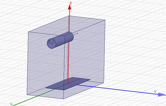
Figure 2: HFSS MODEL
S-parameters describe the port responses of the model. Equation (1) reproduces the source S-parameter matrix at 1 GHz. These port-coupling quantities should be distinguished from calibrated radiated field-strength measurements.
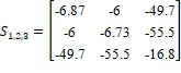 (1)
The reported coupling between ports 1 and 2 differs from the coupling between either PCB receiver and the conductor at port 3. The responses also vary with frequency, particularly above 3 GHz.
Experimental Measurements
The measurements examine ABS and airbag cable samples with different ageing and deterioration levels. The equipment under test (EUT) is operated in a condition intended to produce maximum emissions. It is connected between a network analyser and a 50-ohm load, with the antenna positioned 1 m from the EUT, as illustrated in Figure 3.
The measurements were carried out at an Electromagnetics Research Laboratory engaged in antenna, communication, electronic packaging, EMI and EMC testing activities.
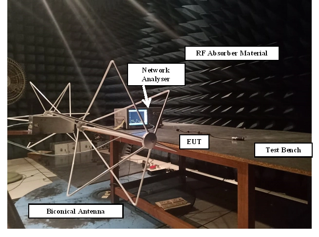
Figure 3: Radiated Emission Measurement
Results and Discussion
Figures 4–6 reproduce the simulated responses for the three port pairs. The source attributes the differences between the conductor-to-PCB responses and the PCB receiver-to-receiver response to termination impedance and coupling conditions. Although the original plot labels use shielding effectiveness, the plotted S-parameters describe port responses.
The responses show substantial variation above 3 GHz. In the port 2–3 response, port 3 represents the transmitter and port 2 the receiver. A comparison of these dB values alone does not establish compliance with radiated-emission field-strength limits.
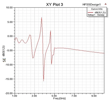
Figure 4: Shielding Effectiveness between ports 1, 2
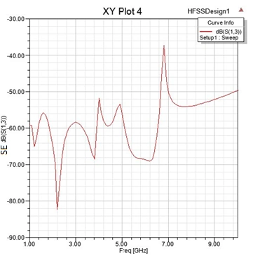
Figure 5: Shielding Effectiveness between ports 1, 3
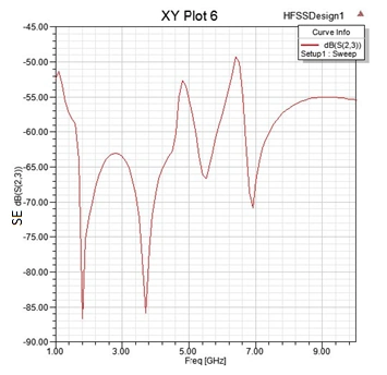
Figure 6: Shielding Effectiveness between ports 2, 3
The experimental measurements cover ABS and airbag cables. A −30 dB reference value was set on the network analyser. Figure 10 reproduces the source illustration of CISPR 25 radiated-emission limits [22]. Its field-strength units differ from the dB labels on the cable plots, so a compliance assessment would also require the applicable calibration, detector, bandwidth, test class and measurement configuration.
ABS Cable Measurements
Figures 7–9 show the ABS cable measurements over 30–300 MHz, 300 MHz–1 GHz and 700 MHz–6 GHz, respectively.
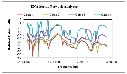
Figure 7: Radiated Emission of ABS cable in 30 MHz – 300 MHz range
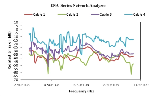
Figure 8: Radiated Emission of ABS cable in 300 MHz – 1 GHz range
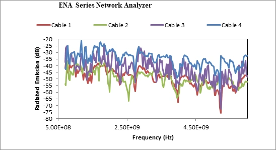
Figure 9: Radiated Emission of ABS cable in 700 MHz – 6 GHz range
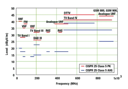
Figure 10: CISPR 25 Radiated Emission limits[22]
The ABS measurements show differences among samples and frequency ranges. Table 1 retains the reported percentage comparisons of cables 2, 3 and 4 with cable 1; these values are relative sample comparisons rather than percentages above a standard limit. Figure 11 reproduces the source comparison plot. The plot and table do not agree in every magnitude, so they should not be treated as independent confirmation of a single numerical result.
Table 1: Comparison of ABS cable measurement
| Frequency Range | Increase in Radiated Emission (%) of cable 2 w.r.t to cable 1 | Increase in Radiated Emission (%) of cable 3 w.r.t to cable 1 | Increase in Radiated Emission (%) of cable 4 w.r.t to cable 1 |
| 30 MHz – 300 MHz | 3% | 32% | 52% |
| 300 MHz – 1 GHz | -11% | 19% | 57% |
| 700 MHz – 6 GHz | -1% | 14% | 29% |
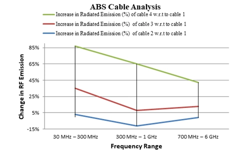
Figure 11: ABS cable comparison
Airbag Cable Measurements
Figures 12–14 show the airbag cable measurements over 30–300 MHz, 300 MHz–1 GHz and 700 MHz–6 GHz, respectively.
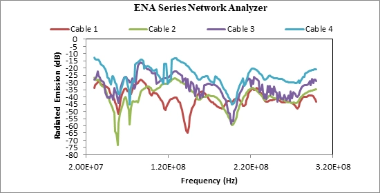
Figure 12: Radiated Emission of Airbag cable in 30 MHz – 300 MHz range
The airbag measurements also differ among samples. Table 2 compares each sample with cable 1, and Figure 15 reproduces the corresponding source plot. The percentages are reported sample comparisons. They should not be read as a calibrated determination of how far a sample exceeds CISPR 25 limits.
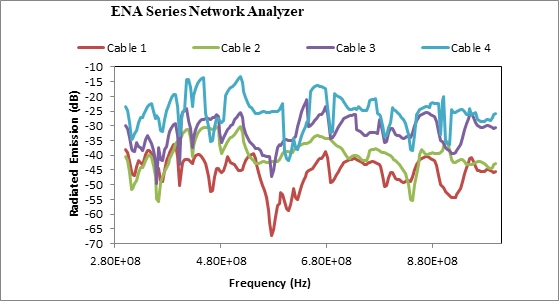
Figure 13: Radiated Emission of Airbag cable in 300 MHz – 1 GHz range
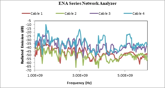
Figure 14: Radiated Emission of Airbag cable in 700 MHz – 6 GHz range
Table 2: Comparison of Airbag cable measurement
| Frequency Range | Increase in Radiated Emission (%) of cable 2 w.r.t to cable 1 | Increase in Radiated Emission (%) of cable 3 w.r.t to cable 1 | Increase in Radiated Emission (%) of cable 4 w.r.t to cable 1 |
| 30 MHz – 300 MHz | 1% | 19% | 37% |
| 300 MHz – 1 GHz | 12% | 29% | 46% |
| 700 MHz – 6 GHz | -7% | 20% | 27% |
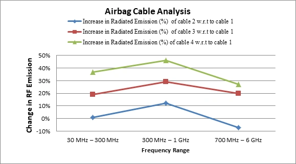
Figure 15: Airbag cable comparison
Conclusion
The simulation and measurements illustrate the frequency-dependent electromagnetic behaviour of automotive cables and the importance of maintaining shield and connector integrity. The experiments cover the stated frequency ranges up to 6 GHz and compare ABS and airbag cable samples at different deterioration levels. The results support further investigation of ageing and termination effects, while the inconsistent ABS comparison magnitudes and the distinction between network-analyser responses and field-strength limits constrain quantitative interpretation. Reliable vehicle EMC assessment requires appropriate shielding design, maintained connections and a documented compliance measurement procedure.
References
G. Bhuvaneswari, S, Manivannan, S, PandiSabareeswari, Shielding
Effectiveness of Enclosures-A Review, Int. J. Appl. Eng. Res. 10 (68)
(2015) 428–430.H.W. Ott, Electromagnetic Compatibility Engineering, John Wiley
and Sons, (2009).Paul and Clayton R, Introduction to Electromagnetic Compatibility
{Wiley Series in Microwave and Optical Engineering; 2nd Ed},
(2006).Y.M. Yang, H.M. Peng, and Q. Di Wang, Common model EMI prediction
in motor drive system for electric vehicle application, J. Electr. Eng.
Technol. 10 (1) (2015) 205–215.Pablo Moreno-Torres et al., Passenger Exposure to magnetic fields
in Electric Vehicles, in IntechOpen, (2016): pp. 47–71.R. Felgenhauer, Electromagnetic interference (EMI) in E-vehicles,
(2011).J. Pulomena, Charged EVs | Dealing with EMC filtering in today’s
electric and hybrid vehicles, (2017).K. Tong Chau et al., State-of-the-Art Electromagnetics Research
in Electric and Hybrid Vehicles, Prog. Electromagn. Res. 159 (2017)
139–157.Y.K.K. Pyoung-Chan Lee, Bo-Ram Kim, Sun Kyoung Jeoung,
Electromagnetic interference shielding effectiveness of polypropylene /
conducting fiber composites, AIP Conf. Proc. 1713 (March) (2016)
120015-1-120015–4.P.K.P. De Melo et al., Analysis of Electromagnetic Interference
in Electric Vehicle Cables, in 2018 IEEE Antennas Propag. Soc. Int.
Symp. Usn. Natl. Radio Sci. Meet. APSURSI 2018 – Proc., (2018): pp.
1393–1394.K. Sunaga, K. Miyajima, and Y. Miyazaki, Electromagnetic Noise
Analysis of High-Voltage Wiring Harnesses, SEI Tech. Rev. 79 (2014)
28–33.F. Gao et al., Improvement of Low-Frequency Radiated Emission in
Electric Vehicle by Numerical Analysis, J. Control Sci. Eng. 2018 (10)
(2018) 1–9.C. Wu et al., A Topology-Based Approach to Improve Vehicle-Level
Electromagnetic Radiation, Electronics 8 (364) (2019) 1–13.G. Li, Cable analysis for electromagnetic compatibility issues,
Missouri University of Science and Technology, 2016.S. Mortazavi et al., EMC Analysis of Shielded Twisted Pair and
Shielded Parallel Pair Transmission Lines for Automotive Multi-Gig
Ethernet, in IEEE Int. Symp. Electromagn. Compat. Signal Power
Integrity, EMC+SIPI 2019, IEEE, New Orleans, LA, USA, (2019): pp.
193–198.S. Bhuvaneswari, P. Salil, and S. Manivannan, Study on shielding
effectiveness of electronic enclosures with connected accessories under
corrosive environment for automobile industry, in Prog. Electromagn.
Res. Symp., Singapore, (2017): pp. 1790–1793.S. Sawada, A. Shimizu, and Y. Saitoh, Deterioration analysis of
automotive connectors used in high mileage vehicles, SEI Tech. Rev. (81)
(2015) 10–15.M. Meyer and P. Asfaux, Radiated emissions modelling of a power
cable, in IEEE Int. Symp. Electromagn. Compat., Institute of Electrical
and Electronics Engineers Inc., Hamburg, Germany, (2008): pp.
1–5.Y. Zheng et al., An equivalent model for wiring harness induced
current in automobiles, Appl. Comput. Electromagn. Soc. J. 28 (11)
(2013) 1088–1099.H. Hackl et al., The shielding effect of a multi-cable harness as
function of IC output termination impedance, in IEEE Int. Symp.
Electromagn. Compat. 2018 IEEE Asia-Pacific Symp. Electromagn. Compat.
EMC/APEMC 2018, IEEE, (2018): pp. 707–712.M. Saih, H. Rouijaa, and A. Ghammaz, Circuit models of lossy
coaxial shielded cables to analyze radiated and conducted
susceptibilities with unmatched line loads, J. Microwaves, Optoelectron.
Electromagn. Appl. 16 (2) (2017) 351–362.T. Hegarty, An overview of radiated EMI specifications for power
supplies, (2018) 1–10.S. Bhuvaneswari, S. Manivannan and P. Salil. Prediction of Shielding Effectiveness of Cables used for Automobile Sector Technical Note. International Journal of Vehicle Structures and Systems 11(1) (2019), 33–35. https://doi.org/10.4273/ijvss.11.1.07
Cite This Work
To export a reference to this article please select a referencing stye below:

Academic Master Education Team is a group of academic editors and subject specialists responsible for producing structured, research-backed essays across multiple disciplines. Each article is developed following Academic Master’s Editorial Policy and supported by credible academic references. The team ensures clarity, citation accuracy, and adherence to ethical academic writing standards
Content reviewed under Academic Master Editorial Policy.