4.1 Introduction
Solar energy is a readily available and cost-free source of energy, recognized for its cleanliness and abundant nature, making it a prominent renewable energy choice globally. Many countries have embraced large-scale solar photovoltaic (PV) installations to mitigate the environmental harm and carbon emissions linked to fossil fuels.[1] Nevertheless, the fluctuating nature of solar energy resources poses challenges for effectively managing the electrical grid as solar energy penetration increases. Additionally, the inherent unpredictability and intermittency of numerous PV power plants can disrupt the overall stability of the power system. It’s important to note that accurate PV power forecasting plays a pivotal role in addressing these issues and optimizing the planning and modelling of solar PV power plants within the power system.
In recent years, there has been a surge of interest among researchers worldwide in the field of PV (Photovoltaic) power generation. The methods employed for PV power prediction can be broadly categorized into three distinct approaches: the physical method, the statistical method, and the artificial intelligence method. Artificial intelligence has a profound impact on various aspects of the energy domain. It contributes to the development of control systems, enhances energy consumption analysis, aids in pattern recognition, and assists in failure classification. Notably, with the rapid advancement of artificial intelligence algorithms and their proven performance across diverse fields, they exhibit superiority in handling non-linear problems characterized by strong uncertainties when compared to other models.
This paper introduces an innovative solution in the form of an algorithm known as the Recurrent Neural Network (RNN). This algorithm is designed to control the PV-integrated distribution grid system effectively, with a primary focus on enhancing its performance and power quality. The core objective of the RNN algorithm is to regulate the Voltage Source Converter (VSC) within the PV-integrated distribution grid. It achieves this by addressing several critical aspects [2]:
Firstly, it actively minimizes unwanted electrical harmonics, ensuring a stable and clean power supply. Secondly, it employs advanced techniques to balance loads effectively across the grid, preventing overloads or underutilization for optimal energy distribution and system stability. Thirdly, it addresses power quality issues such as voltage fluctuations and frequency variations, enhancing the overall quality of power supplied by the PV-integrated grid. Finally, the algorithm optimizes the grid-side Voltage Source Converter (VSC) to maximize the delivery of PV-generated power, resulting in an overall increase in energy output. This multifaceted approach significantly improves the efficiency, stability, and reliability of PV energy integration into distribution grids.
The suggested method has been developed and tested within a MATLAB environment, utilizing SIMULINK for simulations. The outcomes of these simulations validate that the reduction in Total Harmonic Distortion aligns with the guidelines outlined in the IEEE-519 standard.
4.2 Proposed Methodology
The introduction of the Recurrent Neural Network (RNN) algorithm represents a novel approach to managing PV-integrated distribution grid systems. Its primary objectives encompass addressing issues related to harmonic mitigation, load balancing, and the enhancement of power quality within the system. The application of the RNN algorithm plays a significant role in the generation of voltage source inverter (VSI) pulses, effectively enhancing power quality by injecting opposing harmonics at the point of common coupling (PCC) [3]. Notably, the proposed system adopts the Luo converter topology, incorporating a series of DC-DC boost converters. This topology choice offers several advantages, including the attainment of high power density and the utilization of a straightforward and efficient structure, making it a key component of the system’s design. Also utilized various control methodologies, including the quadratic regulator, Widrow-Hoff algorithm, hybrid controller, ANFIS (Adaptive Neuro-Fuzzy Inference System), and adaptive theory, as part of efforts to enhance power quality.
4.2.1 RNN algorithm
The Recurrent Neural Network (RNN) stands out as a distinct type of neural network that offers a critical feature for tasks involving sequential data [4]. Unlike traditional neural networks, where inputs and outputs are treated independently, RNNs introduce the concept of interdependence and memory across sequential elements[5]. This becomes particularly valuable when predicting the next word in a sentence, as it necessitates a contextual understanding of previous words. The core innovation of RNNs lies in their hidden state, which serves as a memory reservoir, retaining essential information about the sequence of inputs [6]. This state, often referred to as a Memory State, retains knowledge of prior inputs to the network, allowing it to maintain context and continuity in its predictions. It has the ability to utilize the same set of parameters consistently across all inputs or hidden layers, thus executing the same operation on each input. This parameter sharing significantly reduces the complexity of the model compared to other neural network architectures, making RNNs particularly suited for tasks where sequence information and memory are crucial elements of the problem-solving process.
The key characteristic of RNNs is that they share the same set of weights (u, w, and B) across all time steps in the sequence [7]. This allows RNNs to capture temporal dependencies and relationships within sequential data. The hidden state at each time step serves as a kind of memory that accumulates information from previous time steps and combines it with the current input to produce an output or make predictions.
Where [?] represents the hidden state at the current time step, it is usually an activation function that introduces non-linearity into the network. Represents the weight matrix that connects the input to the hidden state. The current input is denoted as. Denotes the weight matrix that connects the previous hidden state to the current hidden state. It is a biased term.
The disruption in voltage and current within an electrical system often stems from the heightened demand created by nonlinear loads [8]. Nonlinear loads, such as those found in various electronic devices, introduce harmonic distortions into the power supply, causing voltage and current fluctuations. Fortunately, there are several mitigation techniques available to enhance power quality in such scenarios. One of the most effective methods involves injecting counteracting harmonics at the Point of Common Coupling (PCC).
To successfully inject these counteracting harmonics, precise control over the voltage source inverter (VSI) is essential. This requires generating accurate reference currents that align with the desired harmonic profile. In the context of this work, a Recurrent Neural Network (RNN) has been proposed as a solution to generate the necessary pulse patterns for the VSI. RNNs, with their ability to model temporal dependencies and adapt to changing conditions, offer a promising approach to achieving the required level of accuracy in generating these pulses. Moreover, the DQ (Differential-Quadrature) method plays a crucial role in this process. It enables the extraction of the actual parameters and characteristics of the electrical grid, which is vital for generating the appropriate reference currents. By applying the DQ method, the system can precisely identify and respond to grid conditions, ensuring that the injected harmonics effectively mitigate the disturbances in voltage and current, ultimately improving power quality.
This algorithm is designed to address time series state problems by using error signals. It operates as a feedback system with backpropagation. The calculation and adjustment of the hidden layer weights are done proportionally to the error’s gradient. However, in situations where the error becomes extremely small and information starts to disappear, there’s a challenge. To tackle this issue, the algorithm combines Long Short-Term Memory (LSTM) with Recurrent Neural Networks (RNN) [9].
The core idea behind this approach is to retain long-term dependencies for a brief period. To achieve this, delay cells are employed to store data temporarily. This algorithm serves the purpose of mitigating harmonics and enhancing voltage stability.
In its structure, it employs a one-to-one system consisting of a forgotten layer, an input layer, an output layer, and a state layer related to the gating mechanism. The input and forget layers of the gate play a significant role in controlling the previous hidden state, which in turn influences the current state [10] [11].
4.2.2 Voltage Source Inverter
A voltage source inverter, or VSI, is a device designed to transform a one-way voltage waveform into a two-way voltage waveform [12]. In simpler terms, it’s a converter that changes its voltage from direct current (DC) to alternating current (AC). In an ideal voltage source inverter, the voltage remains consistent throughout this conversion process. A typical VSI comprises essential components, including a DC voltage source, a switching transistor, and a large DC link capacitor [13][14]. The DC voltage source can vary and be derived from sources such as batteries, dynamos, or solar cells, while the transistor used for switching may be an IGBT, BJT, MOSFET, or GTO.
These inverters are increasingly finding diverse applications, including grid integration for renewable energy sources. In this scenario, a varying DC power source feeds energy into an AC system, maintaining a near-constant voltage level. There exist three primary categories of VSIs: the Single Phase Half Bridge Inverter, the Single Phase Full Bridge Inverter, and the Three Phase Voltage Source Inverter [15].
4.2.2.1 Single phase half bridge inverter
It works as a light switch for electrical power with a single switch to control the flow of electricity in one direction. It converts DC power to AC power in a basic way. It is employed for smaller applications like switching the direction of power flow in household appliances.
4.2.2.2 Single phase full bridge inverter
It works like a double-sided switch that not only turns the power on and off but also switches the direction of the power flow. This type is more versatile and is employed in a wide range of applications.
4.2.2.3 Three-phase voltage source inverter
This is a sophisticated electrical device used for converting DC power into three-phase
AC power. It is employed in various industrial applications. It has the ability to provide precise control over the output voltage and frequency. This is employed in our proposed method.
This inverter consists of a series of semiconductor switching devices, such as insulated gate bipolar transistors or metal oxide semiconductor field effect transistors. These switches rapidly switch DC voltage. It uses a pulse width modulation technique to convert DC into AC voltage. It controls the switching of semiconductor devices to produce the sinusoidal three-phase AC voltage, each with a phase shift of 120 degrees. In practical applications, an output filter is often added to reduce voltage harmonics and smoothen the output waveform. This filter helps ensure that the AC voltage supplied by the VSI closely resembles the ideal sinusoidal waveform, which is important for the proper operation of connected equipment. In our case, we use an LC filter.
Thus, inverters are static devices that transform DC power into AC output waveforms. When the DC input comes from a voltage source, it’s referred to as a Voltage Source Inverter (VSI). VSIs are known for their reliability and capability to manage reactive loads without requiring a freewheeling diode. They are recognized for their enhanced efficiency and dependability, especially when employing Pulse Width Modulation (PWM) techniques to minimize total harmonic distortion and enhance the quality of the output signal. Research has shown that Unipolar Modulation, in particular, results in lower total harmonic distortion and improved power quality.
4.2.3 LC Filter
LC filters are electrical circuits that utilize a combination of inductors (L) and capacitors (C) to selectively allow or block certain frequency ranges within an electric signal. Capacitors act as barriers to direct current but facilitate the flow of alternating current, especially at higher frequencies. On the contrary, inductors allow DC to pass through without impedance but hinder the flow of AC, particularly at higher frequencies. Essentially, capacitors and inductors are passive components with diametrically opposed characteristics. Through the strategic arrangement of these opposing components, LC filters can effectively attenuate unwanted noise while isolating specific desired signals. We have three major types of LC filters: low pass, high pass, and band pass.
4.2.4 LUO converter
Luo converters represent a groundbreaking advancement in DC-DC voltage conversion technology. These innovative boost converters have been developed by Fang Luo based on the voltage lift technique, setting them apart from traditional converters. Their unique positive-to-positive voltage boosting capability, coupled with high power density, efficiency, simplicity, and low output ripple, positions them as a game-changer in the realm of power electronics.
Luo-converters can also be applied effectively in photovoltaic (PV) systems, where they can help optimize energy harvesting, enhance system performance, and improve the overall efficiency of solar power generation. They can be employed as part of the MPPT algorithm in PV inverters. MPPT is essential for extracting the maximum available power from the solar panels by continuously adjusting the operating point of the solar array to the point of maximum power output [16]. Luo-Converters can help efficiently regulate the voltage levels to ensure the PV system operates at or near its peak power output [17] [18] [19]. The output voltage of the solar array may not always match the requirements for grid connection or energy storage. Luo-converters can efficiently regulate and boost the voltage to meet these specific needs [19]. This capability is particularly valuable when connecting multiple solar panels in series to achieve higher voltage levels for grid-tied applications. Integrating Luo-Converters into PV systems with energy storage solutions, such as batteries, is a strategic move to optimize energy management. These converters facilitate efficient charging and discharging processes, enhance energy utilization, and improve system resilience, ultimately making solar power systems more reliable and cost-effective [20]. Their role in maximizing the benefits of energy storage is crucial in harnessing the full potential of renewable energy sources like solar power.
The inductor L1 stores the energy during on-time, and L2 represents the energy during off-time. These are important for energy transfer and storage. Capacitor C1 filters the output voltage, and C2 is used to maintain the voltage level [29] [30]. S is the semiconductor switch that controls the flow of energy between the input and the inductors. The diode provides the path for the inductor current to flow during the off-state. The operation of a Luo-Converter involves the switch turning on and off at a high frequency, allowing energy to flow from the input to the output and then to the output capacitor. The inductors and capacitors store and release energy, resulting in voltage boosting from Vin to Vout.
The evaluation of harmonic fundamental components is central to the control technique being employed. Consequently, the following empirical relationships play a crucial role in shaping the proposed methodology. The universal equation for the current on the load side of the distribution system is articulated in Equation 4.3, encompassing both the fundamental component and the kth harmonic.
4.2.5 STATCOM
A Static Synchronous Compensator (STATCOM) is a reactive compensation device connected in parallel to the transmission networks [21]. It employs power electronics to create a voltage-source converter capable of supplying or absorbing reactive AC power within an electrical network. This device belongs to the category of FACTS (Flexible Alternating Current Transmission System) devices [22]. STATCOMs serve as alternatives to passive, reactive power devices like capacitors and inductors. Unlike these passive components, STATCOMs offer the advantage of adjustable reactive power output, with the ability to rapidly modify their output within milliseconds [23]. Additionally, they are versatile in that they can both supply and absorb both capacitive and inductive reactive power (vars) [24]. While they can be utilized for purposes such as voltage support and power factor correction, their notable speed and flexibility make them particularly well-suited for dynamic scenarios, such as providing grid support during fault conditions or contingency events. Fig. 4.6 shows the structure of STATCOM.
A typical STATCOM configuration includes a multi-level Voltage Source Converter employing Insulated Gate Bipolar Transistors, phase reactors, and a step-up transformer. This setup is connected in parallel to the grid and facilitates the provision or absorption of reactive current by generating a controlled internal voltage waveform. Many of the STATCOMs available in the market today function as Grid-Connected Converters and rely on a grid voltage reference to operate, which requires a defined level of grid strength. In practice, STATCOMs function as AC current controllers, with the control of output current achieved by regulating the amplitude of the internal STATCOM voltage (located behind the phase reactor) [24] [25]. This voltage’s phase angle is typically set close to 90 degrees concerning the grid connection point voltage. When the STATCOM voltage amplitude exceeds the system voltage amplitude, it supplies capacitive reactive power to the grid.
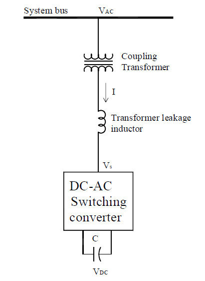
Figure 4.6: Schematic of STATCOM
The heart of a STATCOM is a VSC, typically based on an Insulated Gate Bipolar Transistor [26]. This VSC is responsible for generating the required voltage waveform. Static Synchronous Compensators are increasingly finding applications in photovoltaic systems to enhance their grid integration and overall performance. In PV systems, STATCOMs serve as advanced voltage regulation devices, providing dynamic control of reactive power. One of their key roles is to counteract voltage fluctuations that can occur due to varying sunlight conditions, grid disturbances, or changes in load demand. By injecting or absorbing reactive power, STATCOMs help maintain a stable grid voltage, which is crucial for seamless PV system operation and grid reliability. In addition to voltage regulation, STATCOMs also assist in mitigating the impact of grid disturbances and harmonics. They can rapidly respond to sudden voltage drops or spikes caused by cloud cover or other factors, ensuring that the PV system continues to operate efficiently. Furthermore, STATCOMs can help reduce the harmonic distortion introduced by the PV inverter, improving the quality of power injected into the grid. The integration of STATCOMs in PV systems represents a significant step toward grid-friendly and reliable solar power generation. Their ability to provide dynamic voltage support and mitigate power quality issues contributes to the stability and efficiency of PV systems, making them a valuable asset in modern renewable energy installations. As the demand for clean energy sources grows, STATCOMs are poised to play a crucial role in optimizing the performance of PV systems and facilitating their seamless integration into the electrical grid.
4.3 Result and Discussion
The suggested approach is implemented and tested within the MATLAB/Simulink environment. The investigation of a grid-connected photovoltaic (PV) system featuring the application of a STATCOM (Static Synchronous Compensator) to mitigate harmonics and enhance voltage stability is verified. A Luo converter is employed to augment the output voltage of the PV system. Additionally, the stability of the DC-link and comprehensive current control are managed utilizing a Recurrent Neural Network (RNN).
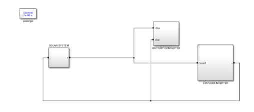
Figure 4.7: Block of the grid-integrated PV system simulation.
Fig. 4.7 is the diagrammatic representation of the simulation block of an integrated photo voltaic system. It is simulated using MATLAB/Simulink. The components involved in the simulation comprise the PV system, the voltage source converter (VSC), the STATCOM inverter, the Luo converter, and various other pertinent elements. These components are interconnected within the simulation setup to emulate the PV system’s connection to the distribution grid. Furthermore, this configuration facilitates the control and supervision of power quality concerns like harmonics and voltage stability.
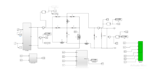
Figure 4.8: Simulation block of PV system with solar and its converter integrated into the grid
Fig.4.8 is the schematic representation of the simulation block of a PV system with solar and its converter integrated into the grid. This particular component serves the purpose of emulating the functions and attributes of the solar panel. It simulates the generation of DC power from sunlight. Concurrently, the converter module is employed to transform the DC power generated by the solar panel into AC power that can be injected into the distribution grid. The simulation of this module provides a means for researchers to scrutinize the solar panel’s and its converter’s performance across various parameters, encompassing power generation, efficiency, and voltage stability. By analysing the outcomes produced by this simulated element, researchers can gauge the efficacy of the proposed system in seamlessly integrating the PV system with the distribution grid and realizing the anticipated enhancements in power quality.
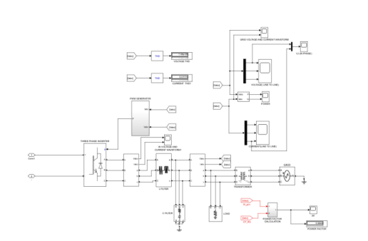
Figure 4.9: Simulation block of PV system with STATCOM inverter integrated into the grid
Fig. 4.9 is the simulation block of the PV system with STATCOM inverter. The STATCOM, or Static Synchronous Compensator, inverter plays a pivotal role in enhancing the voltage stability within the grid-connected PV system. This particular module emulates the functionality and attributes of the STATCOM inverter, including its proficiency in overseeing and managing voltage levels across the system. Researchers can gauge the efficacy of the STATCOM inverter in ameliorating voltage fluctuations and preserving a reliable power supply by scrutinizing the results produced by this simulated module. Through simulation, it becomes possible to thoroughly assess the STATCOM inverter’s performance concerning voltage stability and its broader impact on elevating the overall power quality within the grid-integrated PV system.
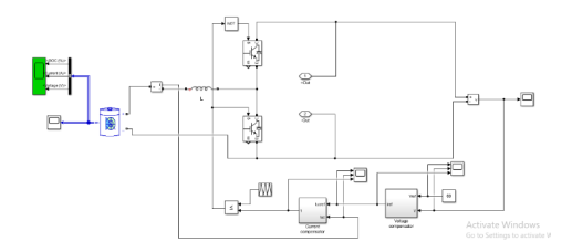
Figure 4.10: Simulation block of PV system with battery and its converter integrated into the grid
Fig. 4.10 emulates the operation and attributes of the battery and its converter within a grid-connected photovoltaic (PV) system. The primary function of the battery and its associated converter is to capture surplus energy produced by the PV system and transform it into readily available AC power when required. Through an examination of the data generated by this simulated component, researchers can assess the effectiveness of the battery and its converter in various aspects, such as their capacity for energy retention, efficiency in energy conversion, and capability to provide power on demand. This analysis enables a comprehensive evaluation of how well these elements function within the larger PV system.
4.3.1 Performance analysis
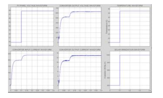
Figure 4.11: Outcome of PV system and LUO converter
Figure 4.11 depicts the power output originating from the PV system and extending through the converter. This visual representation captures the highest level of power generated by the PV system before it proceeds to the subsequent stage. The graph offers a visual insight into the outcomes observed within the DC link, presenting the waveforms of both voltage and current. This graphical representation serves as a valuable tool for scrutinizing the operational characteristics and conduct of both the PV system and the Luo converter, particularly in relation to their capabilities in power generation and the preservation of voltage stability.
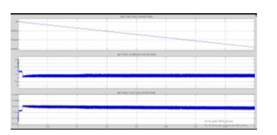
Figure 4.12: DC link output
Fig. 4.12 is the simulated output of the DC line. In a PV-integrated distribution grid system context, monitoring the output across the DC line holds significance as it reflects the system’s efficiency. Through this examination, researchers can assess whether the system is effectively delivering maximum power to the grid-side Voltage Source Converter, aligning with its intended operation. Moreover, this output serves as a valuable indicator for detecting power quality issues like voltage fluctuations or harmonic distortions. Diverse instruments, such as oscilloscopes or multimeters, can be employed to measure it. To validate the accuracy of the proposed technique, the results derived from the DC line’s output can be compared with theoretical calculations or simulations.
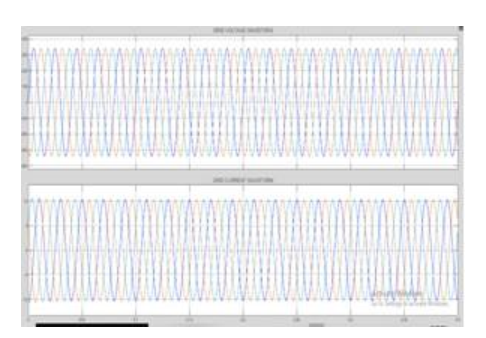
Figure 4.13: Waveform of voltage and current across the grid
Fig 4.13 is the graphical representation of voltage and current waveforms across the grid. Voltage waveforms depict the fluctuation of voltage over time, whereas current waveforms represent variations in current over time. The term “grid side” refers to the section of the distribution grid linked to the primary power grid. Monitoring and regulating voltage and current waveforms are critical parameters for ensuring the efficient operation of PV-integrated distribution grid systems. Through the analysis of voltage and current waveforms, researchers can identify power quality issues like harmonic distortion, voltage fluctuations, or imbalanced currents. Waveform analysis also aids in identifying optimal operational conditions, such as pinpointing the maximum power point for PV panels. To measure voltage and current waveforms, specialized equipment like oscilloscopes or power analysers is used, and the collected data is processed and analysed using software tools like MATLAB or Simulink.
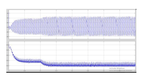
Figure 4.14: Waveform of active and reactive power
Fig. 4.14 is the simulated output waveform of active and reactive power. Active power signifies the practical energy utilized by the load and is quantified in watts. It is accountable for executing productive tasks. Conversely, reactive power represents the energy essential for the load to generate and sustain magnetic fields. It is gauged in volt-amperes reactive and does not contribute to productive tasks. Researchers can assess the efficiency of the system and spot any power quality issues like voltage swings or harmonic distortion by examining these waveforms.
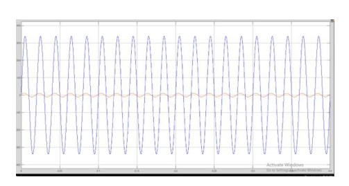
Figure 4.15: Waveform of load current and voltage
Fig. 4.15 shows the simulated waveform of load current and voltage. The load side pertains to the section of the system where power is delivered from the distribution grid and employed to operate a multitude of devices or appliances. The current waveform illustrates the passage of electrical current within the load, while the voltage waveform signifies the electrical potential difference between the load and the distribution grid.
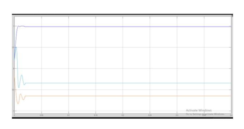
Figure 4.16: Graphical representation of Power factor waveform
Fig. 4.16 is the graphical representation of the waveform of the power factor. Power factor gauges the efficiency of electrical power utilization within a system. It’s quantified as the ratio between real power measured in watts and apparent power measured in volt-amperes. A power factor of 1 signifies optimal utilization, where all supplied power is effectively used, while a power factor below 1 indicates some power wastage. It is a graphical representation depicting the variation of power factor throughout a specific time duration. This analysis can identify opportunities for enhancing power factor correction, resulting in improved efficiency and potential cost reductions.
4.3.2 Analysis of THD and Settling Time
Table 4.1: Comparing THD and settling time
| Parameters | PI | DQ | RNN |
| Settling time | 3 | 2.5 | 1.65 |
| THD | 4.6% | 4.1% | 2.5% |
The THD and settling time values for the PI controller, DQ controller, and RNN algorithm are tabulated and compared in Table 4.1. Settling time denotes the duration needed for a system to stabilize following a disturbance. THD, or Total Harmonic Distortion, quantifies the level of signal distortion caused by harmonics.
The RNN algorithm exhibits the swiftest settling time at 1.65 seconds, with the DQ algorithm following at 2.5 seconds and the PI algorithm at 3.0 seconds. In terms of THD, the RNN algorithm showcases the least distortion at 2.5%, trailed by the DQ algorithm at 4.1% and the PI algorithm at 4.6%. The RNN algorithm stands out as the most effective option, delivering the quickest settling time and the most substantial THD reduction. In contrast, the PI algorithm exhibits both the lengthiest settling time and the highest THD, suggesting it might not be the optimal choice for overseeing the PV-integrated distribution grid system. While the DQ algorithm surpasses the PI algorithm in settling time and THD performance, it still falls short of the efficiency achieved by the RNN algorithm.
The simulation outcomes demonstrate that the suggested approach successfully lowers Total Harmonic Distortion (THD) in compliance with the IEEE-519 standard. This underscores the algorithm’s effectiveness in enhancing power quality within the PV-integrated distribution grid system on the load side.
4.4 Summary
The work introduces an innovative control algorithm known as Recurrent Neural Network (RNN) for the management of Photovoltaic (PV) integrated distribution grid systems. This algorithm specifically emphasizes addressing challenges related to harmonic mitigation, load balancing, and overall enhancements in power quality. Its primary objective is to optimize power delivery through the grid-side Voltage Source Converter (VSC) while simultaneously adhering to the IEEE-519 standard by reducing Total Harmonic Distortion. This proposed technique is meticulously developed and subjected to simulation using MATLAB and SIMULINK. The simulation results unequivocally affirm the algorithm’s efficacy in diminishing Total Harmonic Distortion, underlining its potential to enhance power quality within PV-integrated distribution grid systems. The paper also highlights the incorporation of the Luo converter topology within the proposed system. This choice contributes to achieving exceptional power density while maintaining a straightforward structural design, further enhancing the system’s appeal and efficiency.
The RNN control algorithm exhibits versatility in managing multiple nonlinear loads at the Point of Common Coupling (PCC). Its design prioritizes simplicity in execution and control techniques, ensuring ease of implementation. The RNN algorithm serves a dual purpose by supplying power to nonlinear loads at PCC and transferring surplus energy to the distribution grid [27]. In instances of voltage sags, the RNN algorithm plays a vital role in maintaining voltage levels by injecting a specific amount of reactive power, thus elevating voltage within operational thresholds [28]. To ensure optimal utilization of the RNN system, the STATCOM (Static Synchronous Compensator) steps in to provide power when sunlight is unavailable. The performance of the RNN algorithm undergoes validation through simulation conducted within a MATLAB environment. This facilitates testing under diverse, challenging environmental conditions, including variations in solar irradiation, unbalanced loads, voltage fluctuations, and grid distortions. The simulation results confirm that the Total Harmonic Distortion of grid currents remains within the IEEE-519 standard limits, affirming the effectiveness of the RNN algorithm in managing the PV-integrated distribution grid system.
The proposed technique aims to inject both active and reactive power into the distribution grid to meet global photovoltaic (PV) demand and is designed to function efficiently across various separation levels. It aligns with the IEEE standard, targeting a Total Harmonic Distortion (THD) of less than 5% to ensure the PV-integrated distribution grid operates within acceptable harmonic distortion limits. Unity power factor operation, achieved by maintaining zero reactive power, enhances overall efficiency. Employing the Recurrent Neural Network (RNN) algorithm for Voltage Source Converter (VSC) control enables adjustable system voltage regulation, ensuring grid stability. Ultimately, the method prioritizes a fast and reliable grid-integrated PV system that responds promptly to changes while maintaining operational efficiency and mitigating power quality issues.
References:
Alsharif, A., Ahmed, A., Khaleel, M., Hebrisha, H., Almabsout, E., Abou Sif, M. and Al-Naas, Y., 2023. Applications of Solar Energy Technologies in North Africa: Current Practices and Future Prospects. International Journal of Electrical Engineering and Sustainability (IJEES), pp.164-173.
Bana, P.R. and Amin, M., 2021, October. Adaptive vector control of grid-tied vsc using multilayer perceptron-recurrent neural network. In IECON 2021–47th Annual Conference of the IEEE Industrial Electronics Society (pp. 1-6). IEEE.
Nair, D.R., Nair, M.G. and Thakur, T., 2022. A smart microgrid system with artificial intelligence for power-sharing and power quality improvement. Energies, 15(15), p.5409.
SaiSindhuTheja, R. and Shyam, G.K., 2021. An efficient metaheuristic algorithm-based feature selection and recurrent neural network for DoS attack detection in a cloud computing environment. Applied Soft Computing, 100, p.106997.
Cheng, L., Khalitov, R., Yu, T., Zhang, J. and Yang, Z., 2023. Classification of long sequential data using circular dilated convolutional neural networks. Neurocomputing, 518, pp.50-59.
Xueqing, Z., Zhansong, Z. and Chaomo, Z., 2021. Bi-LSTM deep neural network reservoir classification model based on the innovative input of logging curve response sequences. Ieee Access, 9, pp.19902-19915.
Li, S., Li, W., Cook, C. and Gao, Y., 2019. Deep independently recurrent neural network (indrnn). arXiv preprint arXiv:1910.06251.
Meraj, S.T., Yahaya, N.Z., Hasan, K., Lipu, M.H., Elavarasan, R.M., Hussain, A., Hannan, M.A. and Muttaqi, K.M., 2022. A filter less improved control scheme for active/reactive energy management in fuel cell integrated grid system with harmonic reduction ability. Applied Energy, 312, p.118784.
Lin, K., Peng, J., Gu, F.L. and Lan, Z., 2021. Simulation of open quantum dynamics with bootstrap-based long short-term memory recurrent neural network. The Journal of Physical Chemistry Letters, 12(41), pp.10225-10234.
Jiang, K., Han, Q., Du, X. and Ni, P., 2021. Structural dynamic response reconstruction and virtual sensing using a sequence to sequence modeling with attention mechanism. Automation in Construction, 131, p.103895.
Li, M., Wang, Y., Wang, Z. and Zheng, H., 2020. A deep learning method based on an attention mechanism for wireless network traffic prediction. Ad Hoc Networks, 107, p.102258.
Sahoo, B., Routray, S.K., Rout, P.K. and Alhaider, M.M., 2021, October. Neutral Clamped Three-level Inverter based Fractional Order Filter Design for Power Quality Advancement. In 2021 International Conference in Advances in Power, Signal, and Information Technology (APSIT) (pp. 1-6). IEEE.
Menzi, D., Bortis, D. and Kolar, J.W., 2021. EMI filter design for a three-phase buck–boost y-inverter VSD with unshielded motor cables considering IEC 61800-3 conducted and radiated emission limits. IEEE Transactions on Power Electronics, 36(11), pp.12919-12937.
Pardhi, P.K., Sharma, S.K. and Chandra, A., 2020, October. Solar photovoltaic roof-top system design and control employing high gain DC converter. In 2020 IEEE Industry Applications Society Annual Meeting (pp. 1-6). IEEE.
Pires, V.F., Cordeiro, A., Foito, D., Silva, J.F. and Romero-Cadaval, E., 2023. Cascaded Multilevel Structure with Three-Phase and Single-Phase H-Bridges for Open-End Winding Induction Motor Drive. IEEE Open Journal of the Industrial Electronics Society.
Mahato, G.C. and Choudhury, T.R., 2020, December. Study of MPPT and FPPT: A brief comparison. In 2020 IEEE 17th India Council International Conference (INDICON) (pp. 1-7). IEEE.
Arumugam, S. and Logamani, P., 2019. Modeling and adaptive control of modified LUO converter. Microprocessors and Microsystems, 71, p.102889.
Darcy Gnana Jegha, A., Subathra, M.S.P., Manoj Kumar, N., Subramaniam, U. and Padmanaban, S., 2020. A high gain dc-dc converter with grey wolf optimizer based MPPT algorithm for PV fed BLDC motor drive. Applied Sciences, 10(8), p.2797.
Sivarajeswari, S. and Kirubakaran, D., 2019. Design and development of efficient Luo converters for DC micro grid. The International Journal of Electrical Engineering & Education, p.0020720919845152.
Meshael, H., Elkhateb, A. and Best, R., 2023. Topologies and Design Characteristics of Isolated High Step-Up DC–DC Converters for Photovoltaic Systems. Electronics, 12(18), p.3913.
Aneke, N.E. and Ngang, N.B., 2021. Improving the Efficacy of the Nigerian Electric Power Transmission Network Using Static Synchronous Compensator (STACOM). Journal of Information Engineering and Applications,(JIEA), 11(2).
Baby, H., Jayakumar, J., Mathew, M., Hussien, M.G. and Kumar, N.M., 2022. Analysis of reactive power loadability and management of flexible alternating current transmission system devices in a distribution grid using whale optimization algorithm. IET Renewable Power Generation.
Boghdady, T.A. and Mohamed, Y.A., 2023. Reactive power compensation using STATCOM in a PV grid connected system with a modified MPPT method. Ain Shams Engineering Journal, 14(8), p.102060.
Dash, S.S. and Mohapatra, S.K., Subject: Flexible AC Transmission System (FACTS).
Duan, Q., Sheng, W., Sha, G., Li, Z., Zhao, C., Li, P. and Ma, C., 2020. Operation scheme for MMC-based STATCOM using modified instantaneous symmetrical components. Turkish Journal of Electrical Engineering and Computer Sciences, 28(1), pp.468-484.
Li, G. and Liang, J., 2022. Modular multilevel converters: Recent applications [History]. IEEE Electrification Magazine, 10(3), pp.85-92.
Paredes, H.K.M., Rodrigues, D.T., Cebrian, J.C. and Bonaldo, J.P., 2021. CPT-Based Multi-Objective Strategy for Power Quality Enhancement in Three-Phase Three-Wire Systems Under Distorted and Unbalanced Voltage Conditions. IEEE Access, 9, pp.53078-53095.
Safder, M.U., Sanjari, M.J., Hamza, A., Garmabdari, R., Hossain, M.A. and Lu, J., 2023. Enhancing Microgrid Stability and Energy Management: Techniques, Challenges, and Future Directions. Energies, 16(18), p.6417.
Santhoshi, B.K., Lakshmi, D., Kumar, R.T., Patwa, S., Lins, A.W. and Matcha, M., 2023, August. Type-2 Fuzzy Logic Algorithm Based High Gain Improved Luo Converter for EV Applications. In 2023 International Conference on Circuit Power and Computing Technologies (ICCPCT) (pp. 1722-1729). IEEE.
Khan, F., Zaid, M., Tariq, A. and Khan, M.M.A., 2023. A new non-isolated high-gain DC-DC converter for the PV application. e-Prime-Advances in Electrical Engineering, Electronics and Energy, 5, p.100198.
Cite This Work
To export a reference to this article please select a referencing stye below:

Academic Master Education Team is a group of academic editors and subject specialists responsible for producing structured, research-backed essays across multiple disciplines. Each article is developed following Academic Master’s Editorial Policy and supported by credible academic references. The team ensures clarity, citation accuracy, and adherence to ethical academic writing standards
Content reviewed under Academic Master Editorial Policy.