Objectives
The primary objectives of this lab are:
- To generate digital signals with addition of noise
- To build a zero crossing threshold detector
Abstract
This experiment is about the generation of digital signals which have noise content added in them and making a digital threshold detector. Thus, this lab will help in understanding the concept of noisy signals and will assist in comprehending the underlying design of digital threshold detector. This report, however, caters the part of experiment till generation of a noisy digital signal. Simple square wave is used to simulate digital signal and noise generator, and the adder is being used for addition of noise in the digital waveform.
Introduction
Noise is the unwanted content that gets added up in a signal during its storage, transmission or processing. In real scenarios, no signals that are transmitted are free of noise. Noise causes the signals to distort, and in case of the significant content of noise, a signal might lose its meaning, and hence errors are caused. There can be numerous causes of noise, for example, noise can be caused due to heating up of electronic equipment or due to electrostatic discharges etc. The first part of this lab will help in generating digital signals with added noise using National Instruments LabVIEW and NI ELVIS II+ Emona Telecom Trainer.
The second part of this lab deals with building the zero crossing threshold detector, which is used to detect the transition of the signal from positive voltage level to the negative voltage level and vice versa (Sound.whsites.net, 2018). A comparator embedded in the lab workstation (NI ELVIS II+ Emona Telecom Trainer) will be used to build a digital threshold detector, by providing the noisy signal at one of its input and connecting the other input to the ground.
The following discussion will only be related to the first part of the experiment that is the generation of a digital signal with the addition of noise.
Requirements
A square wave is to be generated with frequency 1 kHz and amplitude +/- 2.5 Volts to simulate a digital signal. This wave then needs to be added with noise. The final signal to be produced is a square wave with an amplitude of +/- 2.5 Volts and signal to noise ratio of 5.
Procedure
The first step is to generate a square wave using a function generator. The amplitude of the function generator is set to be 2.5 volts and frequency knob is set at 1 kHz. In waveform settings, the square wave is selected, and sweep settings include start frequency to be 100 Hz, stop frequency to be 1 kHz, step to be 100 Hz and step interval to be 1000 milliseconds as shown in figure (1) below.
Figure 1: Setting the function generator to produce 1 kHz square wave
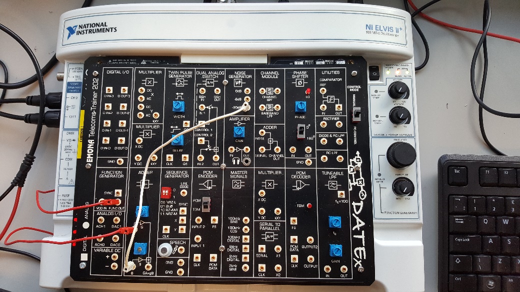
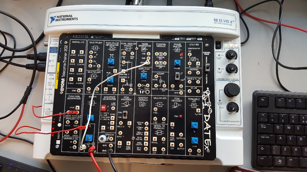
The next step is to add noise to the output of the function generator (FG). The square wave generated is then fed into the adder using a red male to male connector and on the second input of the adder, -20 dB output of noise generator (NG) is connected using a white male to male connector as shown in the figure (2) below.
Figure 2: Connecting FG output to Input A of Adder (Red Link) and connecting -20dB output of NG to Input B of Adder (White Link).
To display the generated square wave with added noise on the oscilloscope, the output of the adder is connected to channel 0 of the oscilloscope using the red probe as shown in figure (3).
Figure 3: Connecting Channel 0 to the output of Adder.
Results and Discussion
The output of this whole experiment is the 1 kHz square wave with an approximate signal to noise ratio of 5. The resultant waveform is displayed on the oscilloscope as shown in the figure below.
Figure 4: Output signal with the SNR approximately equal to 5.
The oscilloscope shows the distorted square wave which is due to the added noise using noise generator. This result indicates that the noise content cause the signal to distort and increased level of distortion is the source of errors in the signal detection.
Conclusion
We can conclude this discussion by the statement that the noise that gets added in the signal during its storage, transmission or processing causes the signals to distort as can be seen in the results of the experiment.
Reference List
- Sound.whsites.net. (2018). Zero Crossing Detectors. [online] Available at: http://sound.whsites.net/appnotes/an005.htm [Accessed 11 Feb. 2018].


