Background
A vending machine is a machine that releases merchandise to a user once the user deposits money and has been validated to be sufficient enough to purchase it. They come in different models and formats. Vending machines in modern life have become easily accessible as they are found everywhere, including places such as airports, business centers, and even leisure facilities. They are convenient and offer 24-hour daily services. Vending machines offer a wide range of commodities, including books, snacks, drinks, photographs, transport tickets, and hot food items. With the constant evolution of this technology, new vending machines with advanced features are constantly emerging into the market. Such features include advanced security measures, interactive touch screens, and cashless payment modes. An example of a snack vending machine with the above-advanced features is SC- 500 Automatic Snack Vending Machine. Intelligent vending machine shares have a compound annual growth of nearly 50% in the vending machine market shares, making a total of roughly 2.1 million units. Vending machine sales are based on simple microprocessor technology. This saves on cost as no network connectivity is required and also can be used in a wide area. This project will explore the Matrix Multimedia PIC development platform for designing an embedded system. This system duplicates the operation of a snack vending machine.
Aim
To emulate a program that will duplicate the embedded system within a snack vending machine using Matrix Multimedia E-Block PIC Development system together with the PIC16F877A microcontroller. The microcontroller monitors the system cycle as well as the input and output operations. The inputs are mimicked by pushbutton switches and the transducer. Pushbuttons duplicate the keypad that is used to select the desired snack item. The potentiometer is used to imitate the output of the tilt-sensor. This is used for anti-theft detection. System outputs are duplicated by the LCD and LEDs boards. LCD display provides the user with information on the operations of the machine in alphabetical order, and LEDs boards duplicate the coin dispensing mechanism and servo motor controller outputs.
Hardware specifications
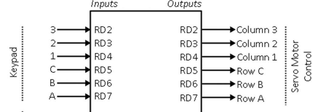
The diagram below outlines both the inputs and output that will duplicate the embedded system found in the vending machine. A typical vending machine has three features: a payment mode, a storage system, and a delivery system.
Operational Specification
There are five primary operating modes during operation. They include;
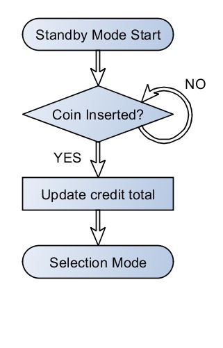
Standby mode
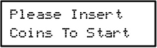
This is the first operating mode where the system is in a stagnant state and appears at start-up. The system waits for the coin to be inserted, and the user is prompted to do so by a simple screen.
Selection mode
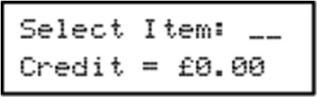
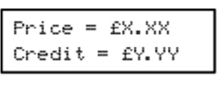
It is entered when a coin is detected in the system. In incidences where the total credit inserted does not match the price of the item, an error message emerges. The initial screen state of this mode is;
The selection mode primarily has three functions.
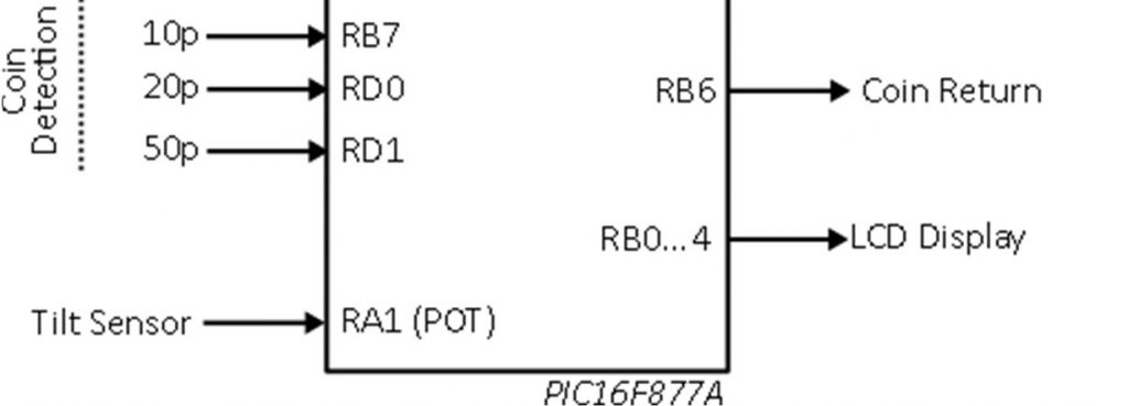
| Coin | E‐Block Pushbutton |
| 50p | RD1 |
| 20p | RD0 |
| 10p | RB7 |
First, coin detection detects the coin inserted and updates the total credits. The detected coins are simulated using,
The system continuously monitors the coin input lines and then updates the total credits inserted.
Second, item selection identifies the item selected using the keypad. The snack items are in a matrix form where the rows are denoted alphabetically and columns numerically. Using the keypad, the user enters the column and row of the desired snack item.
| 1 | 2 | 3 | |
| A | Quavers = 60p | Doritos = 80p | Haribo = £1.40 |
| B | Mars bar = 80p | Twix = 70p | Yorkie = 80p |
| C | Coke = £1.20 | Sprite = £1.00 | Fanta = £1.00 |
| Keypad button | E‐block Pushbutton |
| A | RD7 |
| B | RD6 |
| C | RD5 |
| 1 | RD4 |
| 2 | RD3 |
| 3 | RD2 |
The table below represents how the E-block pushbuttons are mapped to rows and columns in the vending machine;
The above two functions work simultaneously.
Lastly, a credit check ensures there is sufficient credit before releasing the chosen item. After a snack item has been identified, the system then ensures that sufficient credit is inserted and then takes the below actions:
- If the inserted credit is sufficient, the system proceeds to dispense mode
- If the inserted credit is insufficient, the system requests the user to top up. The screen displays show the price of the item together with the current credit while waiting for the user to top up.
Every time a coin is inserted, the credit total is updated until it matches or even exceeds the price of the selected item. The system only moves to dispense mode when the credit inserted is sufficient.
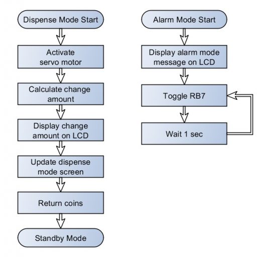
2.4 dispense mode
In this mode, the system dispenses the item that has been selected and any required change with a minimum number of coins. The system, therefore, performs two major functions in this mode.
First, the system operates a servo motor that is connected to a spiral auger so as to distribute the snack item selected. The servo motor is also addressed in a matrix form. The rows are denoted alphabetically and the columns numerically, just like in item selection.
| 1 | 2 | 3 | |
| A | RD7 + RD4 | RD7 + RD3 | RD7 + RD2 |
| B | RD6 + RD4 | RD6 + RD3 | RD6 + RD2 |
| C | RD5 + RD4 | RD5 + RD3 | RD5 + RD2 |
The spiral auger of a snack is displayed by pulsing the necessary PORTD lines three times. During pulsing, the lines should go 2s high and 1s low.
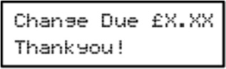
Dispense change
After subtracting the funds of the selected item, the remaining funds are usually returned to the user. The change due is usually displayed by the LCD screen, as shown below. The fund returned are simulated by 1s high followed by 1s low. 0nce the user obtains the coins, the system waits for approximately five seconds and then clears the LCD. The system then returns to standby mode awaiting the next user.
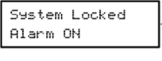
2.5 Alarm Mode
This mode is entered when the analog tilt sensor detects excess moving of the vending machine indicating possible vandalism or theft. This mode is only entered when the voltage exceeds 3 volts. The potentiometer on the E-block sensor board simulates the tilt sensor. Alarm mode may enter at any particular time when the system is operating. When excess movement is detected, the system displays a warning message, and the alarm is activated. The system is then locked down, and it displays the following on the LCD
Further requirements
3.1 Default settings
On reset or power-up, there are certain default settings that are supposed to be used so as to enter a known state. The default settings are;
| Item | The default value at startup |
| Credit | £0.00 |
3.2 Analogue sensor checking
The E-Block sensor board potentiometer should be regularly observed at 50 ms intervals using the Timer 0 overflow interrupt. The interrupt enables constant monitoring of the sensor in all the operational modes.
3.3 Control of LED toggling timing
Toggle output lines to the LED boards simulate the activating of the servo motors as well as change dispensing mechanism. Delays to the above should be managed by using the hardware timer module, Timer 1.
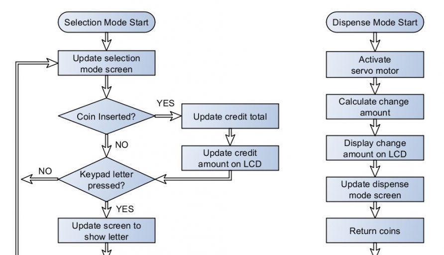
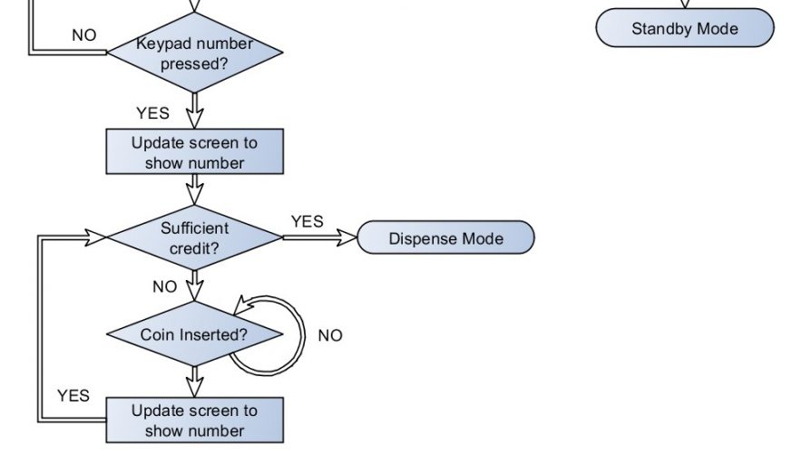
Operational flowcharts
The flow charts below show a summary of the operation of the system.
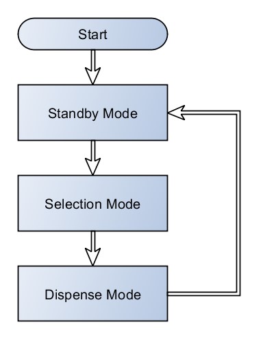
The following high‐level flowcharts summarise the operation eac
h operational mode.